Search
Close this search box.

Overflow valves with thread connection

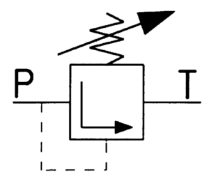
The overflow valves with thread connection are used for actuation type E: with adjustment screw.

The valves are suitable for use with lubricating and hydraulic oils and many other self-lubricating non-corrosive fluids. They deliver excellent heating oils EL, L, M, S and ES, coal tar oils and kerosene.

Technical Data:

Material
casing of hydraulic cast iron (GGG 40); certificate on request; piston, valve tip, spring of hardened steel

Details

  • Maximum temperature of fluid medium: 150 °C.
  • Function: Directly-controlled, spring-loaded overflow valve for maintaining a set operating pressure or a set maximum pressure in a pressure pipe
hp Überströmventile in Gewindeausführung Diagram 1

Summary:
hp-Overflow valve,
flow range: . . . . . (l/h)
pressure stage . . . . , adjustable . . . . . (bar)
Type: . . . . .

TÜV Rheinland
Model Possible pressure stages for
each model
Connection thread 2) Flow range
l/h

Viscosity range

>cSt

Item No.
B – P – E / _ G 1/4″ 1)

0 = 0,5 – 1,5 bar

1 = 1 – 4 bar

2 = 2 – 9 bar

3 = 6 – 25 bar

4 = 15 – 40 bar

G 1/4″ 6 – 120 2,8 bis 480 210000
B – P – E / _ G 3/8″ 15 – 160 2,8 bis 480 210002
B – G – E / _ G 1/2″ 30 – 600 2,8 bis 480 210003
B – GH – E / _ 3) G 3/4″ 100 – 2000 2,8 bis 480 210004
B – GHG – E / _ G 1″ 300 – 6000 2,8 bis 480 210005
B – GHG – E / _ G 1 1/4″ G 1 1/4″ 500 – 10000 2,8 bis 480 210006

1) Not pressure stage 0
2) Pipe thread G…A DIN ISO 228-1
3) Not pressure stage 0, for pressure stage 1: 0.5 – 3.5 bar, all further pressure stages according to table

Kolben mit Axialnut (Schwerölkolben)

For very dirty heavy oils, the overflow valves may be fitted or retrofitted with a piston axial nut (heavy oil piston) at an additional cost.

Model Item No. Ø for piston and hole
BP 840750 20/2,5
BG/FDR 15 840752 20/5,0
BG/FDR 15 840754 20/7,5
BGH/FDR 20 840756 30/10
BGHG 1“/FDR 25 840758 35/15
BGHG 11/4“/FDR 32 840760 35/25
FDR 50 840762 50/30

Model with regulating screw
After removing cover screw 1
on the regulating screw, the pressure is increased by turning clockwise with a screwdriver or with an allen key. It is decreased by turning counterclockwise.

Size Table

Model a b1 c1 d1 d2 f1 max. Pipe NW f2 Adjustment path h at pressure stage
0 + 1 2 3 4
P – 1/4″ 55 65 37 36 52 G 1/4″ 10 x 1 8 G 1/8″ 15 12 8 7
P 55 65 37 36 52 G 3/8″ 12 x 1 10 G 1/8″ 15 12 8 7
G 55 65 37 36 52 G 1/2″ 18 x 1,5 15 G 1/8″ 15 12 8 7
GH 63 65 43 50 70 G 3/4″ 22 x 1,5 20 G 1/4″ 15 10 8 5
GHG 80 62,5 56 56 86 G 1″ 28 x 1,5 25 G 1/4″ 20 17 9 6
GHG – 1 1/4″ 80 62,5 56 56 86 G 1 1/4″ 35 x 2 30 G 1/4″ 20 17 9 6

For installation, operation and maintenance, follow the operating instructions that come with each piece of equipment.

Need additional infos? Please contact us

Jochen Twellaar

+49 (0) 721/95618-23

twellaar@hptechnik.com

Joachim Rau

+49(0) 721/95618-25

rau@hptechnik.com