Home » Assemblies » Pressure Accumulator Units / Suction Aggregates
Your advantages
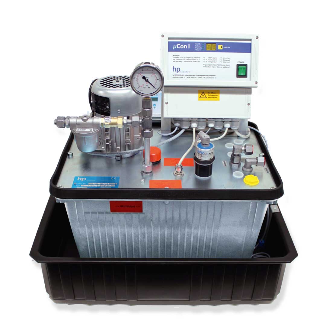
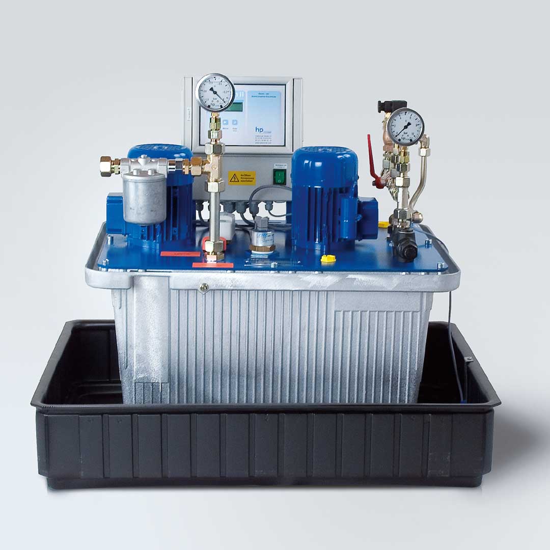
Easy installation (ready to plug in)
Easy commissioning
Easy maintenance
Easy adaptation to different system requirements through programmable control
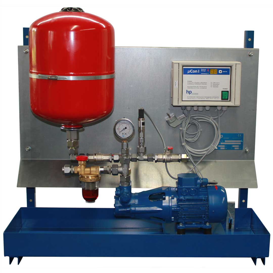
Application
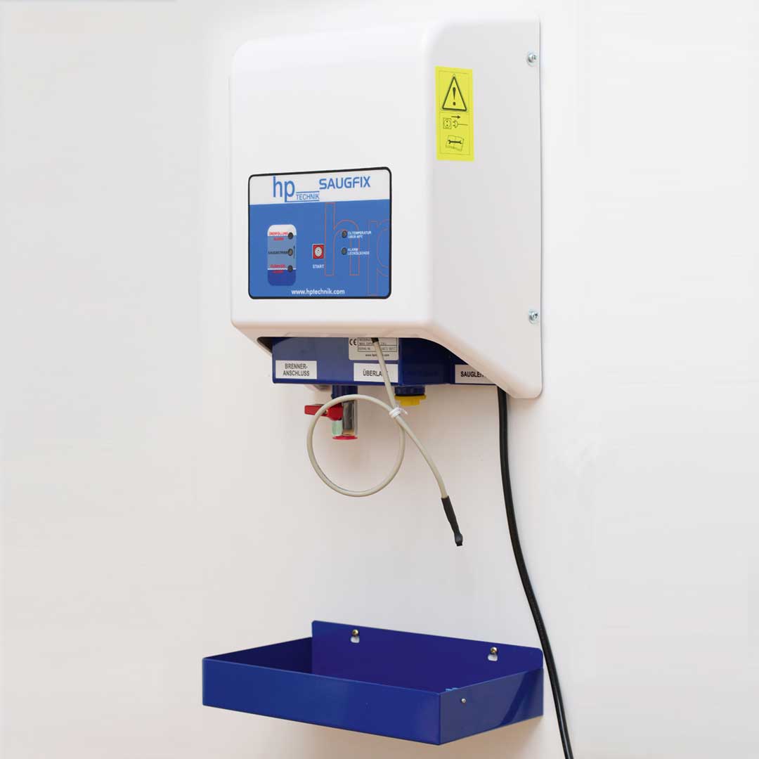
Suction units are used wherever pressure pipes are not permitted, such as:
Pipeline not visible
Underground pipeline
Pipelines that cannot be “walked on”
TÜV requirements
The following information is essential for an exact device selection:
Burner output in [kW] or [I / h]
Number of consumers
Geodetic height difference between the lowest point of the extraction and the highest point of the suction line [m]
extended suction line length [m]
Number of angles and fittings
Arrangement sketch from tank to burner / site plan
What can help with the design:
Permissible flow velocities in suction lines: 0.3 … 0.8 ms-1. The following rule of thumb applies to the determination: C = Q / A with Q [m3s-1] and A [m2]. For the
The delivery rate Q must always use the full delivery rate of the pump! Not the delivery rate according to the selection diagram! See also diagram catalog page 99.
The physically maximum possible suction height: approx. 9.0 m / with a line length of 10 m. The negative pressures to be expected in the suction line are then p≥ -0.9 bar, which is associated with considerable noise development. Residential buildings are excluded from the use of suction units within these limits.
If the tank is higher up, a siphon protection must be provided in the event of a line break. When using solenoid valves, the suction line must always be equipped with appropriate pressure relief devices. Mechanical valves are not suitable for the possible negative pressures that may occur.
The cables must be laid frost-free, if this is not possible, then with trace heating.
Foot valves cannot be used because the line is self-locking, the return of the oil to the tank must be possible in the event of a line break!
When setting up in WHG areas, the units must be equipped with additional overfill protection according to §63 WHG!
A device preselection can be made with the aid of the pump characteristics on page 53. The actual delivery rate of the suction pump is shown here as a function of the suction line length and suction height and the pipe cross-section. The determined delivery rate should always be large enough to compensate for viscosity fluctuations during winter operation.
Suction units find their limits due to the resulting negative pressure in the suction line, which increases proportionally with increasing suction height and line length and thus reduces the effective delivery rate of the pump accordingly.
At high negative pressures, the filling level of the pumps decreases considerably and the noise emission increases. This also results in a reduction in the service life of the pumps.
Durch die Nutzung unserer Website stimmen Sie der Verwendung von Cookies zur Verbesserung des Online-Erlebnisses zu. Mehr Informationen.
By using our website, you agree to the use of cookies to improve the online experience. More Information.