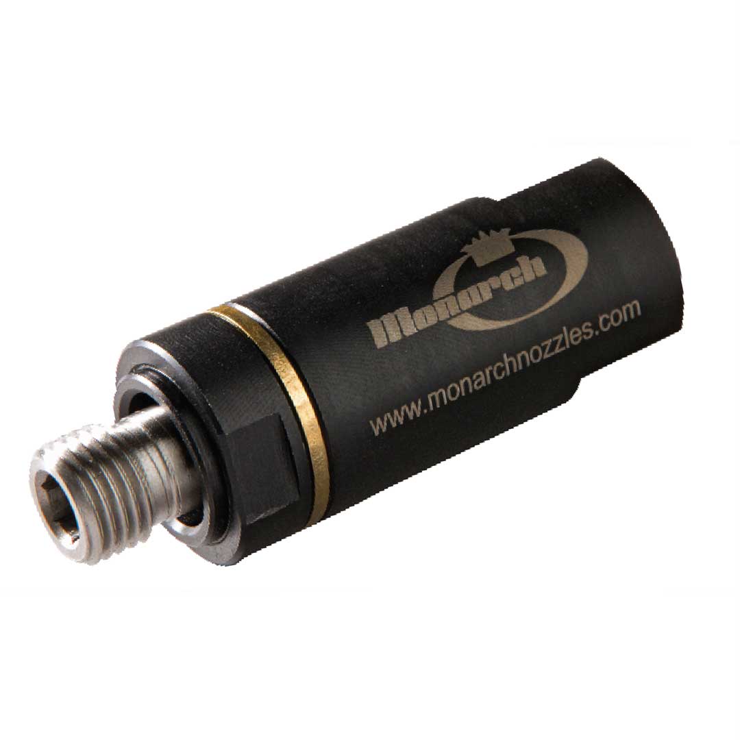
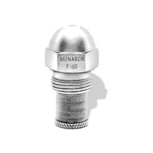
MONARCH oil burners and industrial nozzles are tried and tested a million times around the world on a daily basis.
hpTECHNIK works closely with MONARCH to supply a comprehensive selection of nozzles for all types of pump and system construction applications.
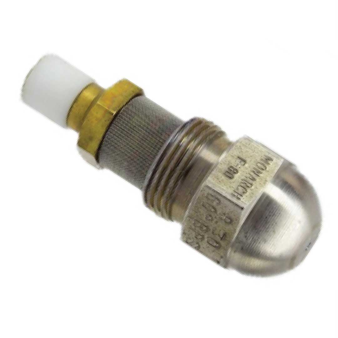
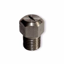
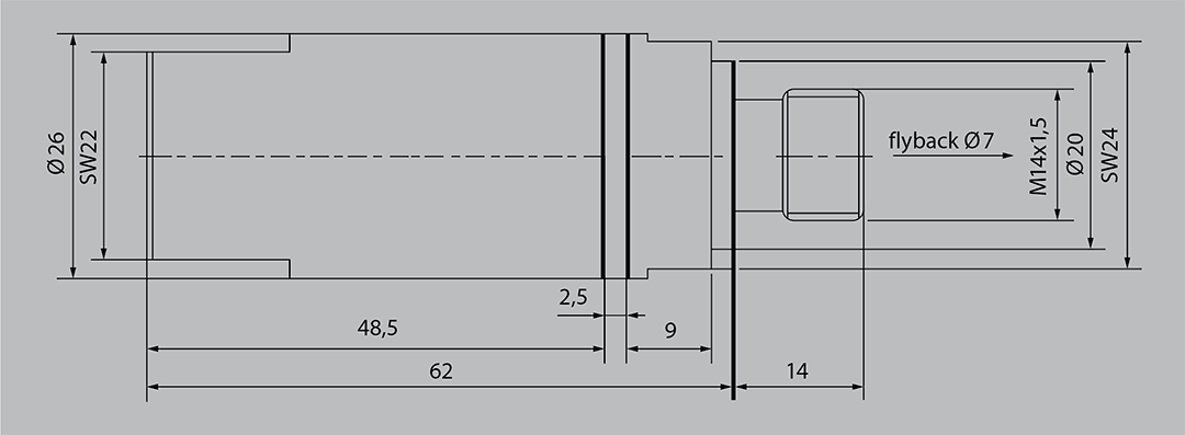
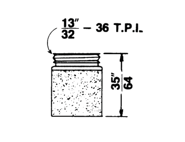
MTD nozzle for EL fuel oil nozzle head and baffle plate made of high-grade chrome steel
In addition to its use for EL heating oil, the MTD series nozzles can be used for all oils whose viscosity does not exceed 5 cst (1.4 ° E). The type MTD-HO (see below) can also be used for oils with a viscosity of up to 13 cst (2.1 ° E).
Selection
The series comprises 72 discharges from 1.5 l/h to 378.5 l/h (0.40 to 100 US GPH).
The use of fuel oil EL at normal operating temperature may vary the discharge by approx. 1%.
The discharge increases with viscosity.
Operating pressure
The nozzles are tested at an operating pressure of 7 bar with fuel oil EL
(see discharge tables on the next page).
The recommended operating pressure for nozzles (for fuel oil EL) is between 6 and 25 bar (please ask for using at higher pressure).
For fluids with a higher viscosity, they can work with an operating pressure of 10 – 14 bar. However, the spray angle decreases drastically (heavily), except if nozzles are used that are specially designed for such applications (see HO nozzle).
Nozzle with porous bronze filters
These filters, where all nozzles are equipped from 0.40 – 1.00 GPH, achieve very good filtering (filter fineness 25 – 50 microns).
This filter has huge advantages to protect the nozzles with small discharges (under 1.00 GPH). The accumulation of small bronze balls forms a series of obstacles, which results in considerably better filtering than for simple screen filters. Therefore, the sensitive internal parts of the small nozzles are better protected. This filter withstands high temperatures.
Nozzle with mesh strainers
Nozzles from 1.10 GPH to 9.5 GPH (4.16 – 39.7 l/h) discharge are all equipped with mesh strainers (Monel), mesh width 120. For larger discharges up to 30 GPH (113.5 l/h), this type of filter can also be used, but is then separately supplied as an extra.
Filtration
Each nozzle is protected by its own filter, the fineness of which is determined by the throughput. Due to its size, however, it cannot guarantee the cleaning of the heating oils on its own. A perfect filtration must therefore be guaranteed upstream of the burner pump in the suction line. We can help with information and recommendations to solve filtration problems.
Installation & Assembly
This process, which will be familiar to a skilled technician, must be carried out according to the following basic rules.
a) The nozzle should not be touched with dirty hands, especially the nozzle bore (the diameter for flow rates below 1.00 GPH is so small that even normal skin exhalation from the hands can clog the nozzle bore).
b) Drain the oil supply. Check the nozzle holder for leaks. Take hold of the new nozzle on the hexagonal part, screw it in by hand and tighten with the nozzle wrench without over tightening.
c) Before commissioning, open the vent screw of the oil pump and allow the oil to run out. This reduces the shock of the start-up and thus prevents possible impurities from being pushed through the nozzle filter by this shock.
d) Minimum pressure to achieve good atomization = 7 bar.
e) Check that the electrode spark does not hit the nozzle.
HO-Heavy Oil Nozzle
This is an extension of the commercially available burner nozzle, which is used especially for the use of heavy oils in the upper permissible viscosity ranges of 5 – 9.5 cst, tested with 430 PSI (30 bar).
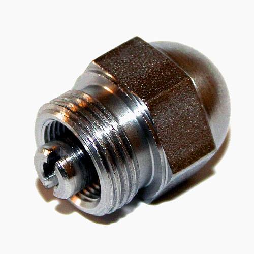
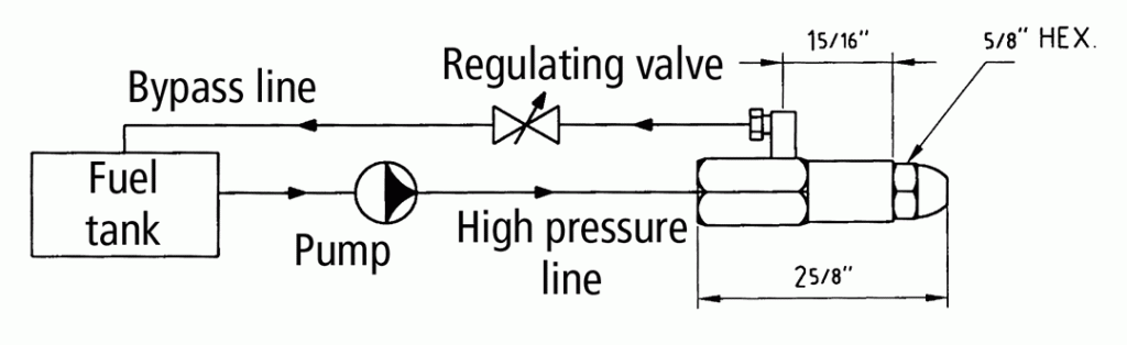
BPS-Bypass nozzle
The BPS nozzles produce variable orifice flow rates by bypassing fluid from the nozzle swirl chamber. The orifice flow is regulated by controlling the by-pass line pressure.
Nozzle tip and disc are made of high quality, heat-resistant stainless steel, the inner fastening cover and the filter body of nickel-plated brass, the Monel mesh strainer with 120µ mesh width for discharges up to 13.50 Gph and 80 µ mesh width for larger discharges.
The seal between the oil inlet and the bypass connection is guaranteed using a viton O-ring.
The BPS bypass nozzles are tested to a pressure of 7 bar with fuel oil EL, viscosity 2.8 cst.
(1.2 ° E). Maximum operating pressure between 17 and 20 bar and max. viscosity of 13 cst. (2.1 ° E).
Industrial Bypass Nozzle Type MO1
Type
Atomization Angle
MO1
30°
125-1000
45° 125-1000
60° 125-1000
80° 125-1000
Standard Output in kg/h
125
200
280
400
650
850
150
225
300
450
675
900
160
250
325
500
700
950
175
260
350
550
750
1000
180
275
375
600
800
Feed pressure: 25 bar I Viscosity 2° E Adjustable Output:
Max.: Return pressure 1 bar
Min.: Return pressure 3 bar
H5 = 1/5 max. output
Delivery: individually in plastic packaging
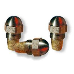
Spray patterns and throughput table
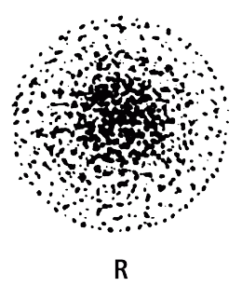
Solid cone “R” series: 0.35 to 3.50 GPH This is the series supplied regularly unless customer specifies otherwise. It is a good all-round nozzle suitable for most burners. Atomization of the oil is not quite as fine as with the “NS” series.
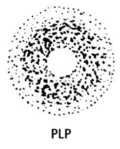
Semi-solid cone “PLP” series: 2.25 to 100.00 GPH The standard nozzle for larger capacities. Fine atomization and “solid” spray pattern up to about 3.50 GPH, gradually becoming more and more “hollow” in the larger sizes.
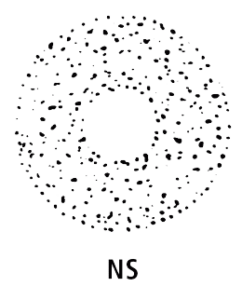
Hollow cons “NS” series: 0.40 to 2.00 GPH This series works best on many burners due to its exceptionally fine atomization.
Produces a quiet stable flame. Widely used in 80 °C and 90 °C on flame retention burners.
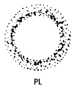
Hollow cone “PL” series: 2.25 to 50.00 GPH This series represents an extension of the “NS” type spray pattern to larger capacity sizes.
Spray is not as finely atomized as the “PLP” series, but produces the best results in equipment specifying hollow cone nozzles.
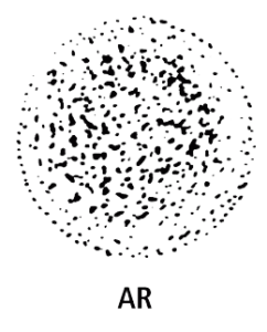
Special solid cone “AR” series: 0.60 to 3.50 GPH This series has become widely used due to its success in obtaining quiet combustion in some flame retention head burners. Traditionally a “cure-all” replacement nozzle, it now is increasingly specified on original equipment.
Narrow spray angle “HV” series: 1.65 to 60.00 GPH Used mostly for Semi-Industrial or Scotch Marine applications where narrow spray angle and high spray velocity is essential and some combustion noise is not objectionable.
Capacity in l/h at a pressure of (bar):
Nominal size
1,0
5,2
7,0
8,8
10,4
12,2
14,0
0,40
–
–
1,51
1,70
1,85
2,00
2,12
0,45
–
–
1,70
1,90
2,07
2,24
2,40
0,50
–
–
1,89
2,12
2,30
2,50
2,68
0,55
–
–
2,08
2,33
2,53
2,75
2,94
0,60
–
–
2,27
2,53
2,80
2,99
3,21
0,65
–
–
2,46
2,76
3,03
3,25
3,48
0,75
–
–
2,83
3,18
3,48
3,74
4,01
0,85
–
–
3,18
3,59
3,93
4,27
4,54
1,00
1,43
3,29
3,78
4,24
4,65
4,99
5,33
1,10
1,57
3,59
4,16
4,65
5,07
5,49
5,86
1,20
1,71
3,93
4,54
5,07
5,56
6,02
6,43
1,25
1,79
4,05
4,73
5,26
5,80
6,24
6,70
1,35
1,93
4,43
5,11
5,71
6,24
6,77
7,23
1,50
2,14
4,92
5,67
6,36
6,96
7,49
8,02
1,65
2,35
5,41
6,24
6,69
7,64
8,25
8,85
1,75
2,50
5,70
6,62
7,42
8,10
8,78
9,38
2,00
2,86
6,55
7,57
8,47
9,27
10,00
10,70
2,25
3,21
7,38
8,51
9,53
10,37
11,30
12,00
2,50
3,57
8,17
9,46
10,60
11,58
12,50
13,40
3,00
4,28
9,80
11,35
12,70
13,93
15,00
16,10
3,50
5,0
11,46
13,24
14,80
16,23
17,50
18,70
4,00
5,71
13,10
15,14
16,90
18,50
20,10
21,40
4,50
6,43
14,76
17,03
19,10
20,80
22,50
24,00
5,00
7,14
16,40
18,90
21,20
23,20
25,00
26,70
5,50
7,86
18,00
20,80
23,30
25,50
27,50
29,40
6,00
8,56
19,60
22,70
25,40
27,70
30,00
32,10
6,50
9,30
21,30
24,60
27,50
30,10
32,50
34,80
7,00
10,00
22,90
26,50
29,60
32,50
35,00
37,50
7,50
10,70
24,60
28,40
31,70
34,80
37,50
40,10
8,00
11,40
26,20
30,30
33,80
37,00
40,20
42,80
8,50
11,85
27,80
32,20
36,00
39,50
42,60
45,70
9,00
12,80
29,50
34,00
38,20
41,60
45,00
48,00
9,50
13,60
31,30
36,00
40,10
44,30
47,70
51,10
10,00
14,20
32,80
37,80
42,40
46,40
50,00
53,40
10,50
15,00
34,40
39,70
44,30
48,80
52,60
56,40
11,00
15,70
36,00
41,60
46,60
51,00
55,00
58,80
Nominal size
Capacity in l/h at a pressure of (bar):
1,1
5,2
7,0
8,8
10,4
12,2
14,0
11,50
16,40
37,80
43,40
48,60
53,30
57,60
61,50
12,00
17,10
39,60
45,20
50,70
55,60
60,20
64,30
12,50
17,80
41,10
47,20
52,80
57,90
62,60
66,90
13,00
18,60
42,60
49,20
55,00
60,20
65,00
69,60
13,50
19,35
44,10
51,10
57,00
62,60
67,80
72,50
14,00
20,00
45,80
53,00
59,20
65,00
70,00
75,00
14,50
20,70
47,50
54,90
61,30
67,30
72,50
77,60
15,00
21,40
49,20
56,80
63,40
69,60
75,00
80,20
15,50
22,20
50,60
58,66
65,60
71,70
77,80
82,80
16,00
22,80
52,40
60,60
67,60
74,00
80,40
85,60
17,00
23,70
55,00
64,40
72,00
79,00
85,20
91,40
17,50
25,00
57,10
66,20
74,20
81,00
87,80
93,90
18,00
25,60
59,00
68,00
76,40
83,20
90,00
96,00
19,00
27,20
62,60
72,00
80,20
88,60
95,40
102,20
19,50
27,80
64,00
73,90
82,50
90,50
97,60
104,50
20,00
28,40
65,60
75,60
84,80
92,80
100,00
106,80
20,50
29,20
67,20
77,50
86,70
95,20
102,60
109,80
21,00
30,00
68,80
79,40
88,60
97,60
105,20
112,80
21,50
30,70
70,40
81,40
90,90
99,90
107,50
115,00
22,00
31,40
72,00
83,20
93,20
102,00
110,00
117,60
23,00
32,80
75,60
86,80
97,20
106,60
115,20
123,00
24,00
34,30
78,70
90,90
101,40
111,30
120,40
128,70
25,00
35,60
82,20
94,40
105,60
115,80
124,40
133,80
28,00
40,00
91,60
106,00
118,50
129,80
140,00
149,90
29,00
41,40
95,00
109,80
122,60
134,60
145,00
155,20
30,00
42,80
98,40
113,50
127,20
139,30
150,30
160,90
35,00
50,00
114,70
132,50
148,00
162,40
175,20
187,40
40,00
57,20
131,00
151,40
169,20
185,50
200,60
213,80
45,00
64,20
147,60
170,30
191,00
209,00
225,20
241,10
50,00
71,30
163,90
189,20
211,60
232,00
250,20
267,60
55,00
78,90
180,20
208,20
232,80
255,10
275,20
294,10
60,00
86,00
196,80
227,10
253,60
278,20
300,50
318,00
70,00
100,40
229,30
255,00
296,00
324,40
350,10
374,70
80,00
114,70
262,00
302,80
338,40
371,00
401,20
429,60
90,00
129,00
294,80
340,60
382,00
418,20
451,20
482,60
100,00
143,40
327,40
378,50
423,50
464,00
500,80
535,20
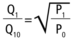
Q0 = flow l/h or kg/h at 7 bar P0 = test pressure for nominal power (generally 7 bar)
The values for the flow table relate to fuel oil EL with an average viscosity of 2.5 – 3 cst (1.18 – 1.22 ° E). 100 PSI = 6.9 bar rounded up to 7 bar. 1 GPH = 3.785 l/h.
The description in the nominal size column is identical to the discharge (GPH) at an operating pressure of 7 bar.
Overfiew additional nozzles
A large range of additional nozzles is available either as a finished product for immediate dispatch or in raw form to be immediately finished according to customer specifications. In cooperation with MONARCH, hpTECHNIK is able to submit orders for special designs at short notice. Our development department is on your side with input and advice for your specific application needs.
Detailed information about other nozzles available for purchase through hpTECHNIK can be found on the Monarch page: www.monarchnozzles.com
Mesh size 120 or 200
MONEL mesh strainer
Porous bronze filter
Tip (stainless steel)
Adaptor (brass)
Remark
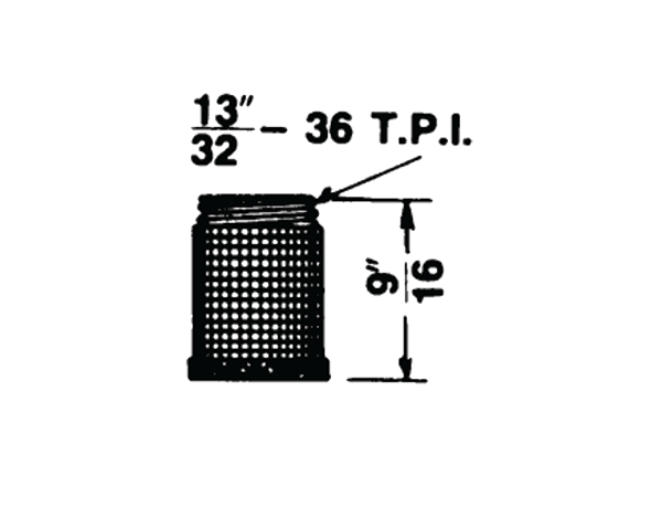
13/32
=
10,3 mm
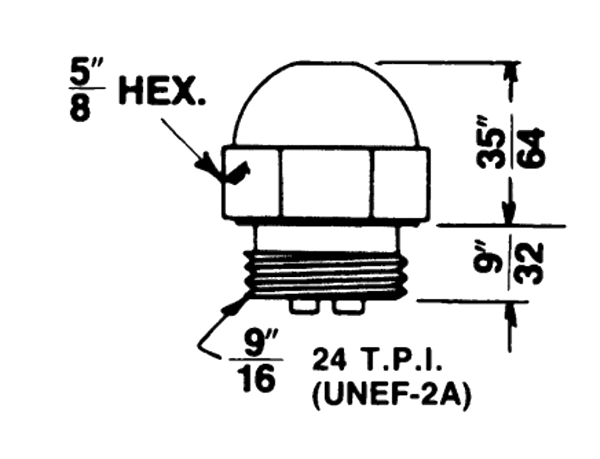
9/16“
=
14,3 mm
9/32“
=
7,1 mm
35/64“
=
13,9 mm
1 3/8“
=
34,9 mm
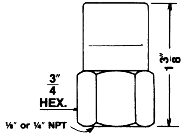
3/4“
=
19,0 mm
1/4“
=
6,3 mm
1/8“
=
3,2 mm
5/8“
=
15,9 mm
T. P. I.: Number of turns per inch
Info
All MONARCH nozzles are stamped with the following characteristics, subject to modification on adoption of CEN standards:
• the flow (in USGPH at l00 PSI = 6.895 bar), (soon, capacity at 10 bar and CEN references);
• spray angle;
• letters to identify the series of spray patterns;
• the, reference MTD-92;
• the, MONARCH trade mark.
Each MTD-92 nozzle is individually tested at several different production stages to assure perfect conformity with master nozzles of each series.
The spray patterns (i.e. hollow cone or solid cone) described below refer to the tests carried out with a 60 °C angle at a 75 mm distance
from the nozzle orifice. In nozzles of 60 °C spray angle or less, and for low flows in particular, the empty section of a hollow cone becomes smaller.
The difference between hollow cone and solid cone practically disappears.
Durch die Nutzung unserer Website stimmen Sie der Verwendung von Cookies zur Verbesserung des Online-Erlebnisses zu. Mehr Informationen.
By using our website, you agree to the use of cookies to improve the online experience. More Information.