Search
Close this search box.

Air-separation unit diagram I & III

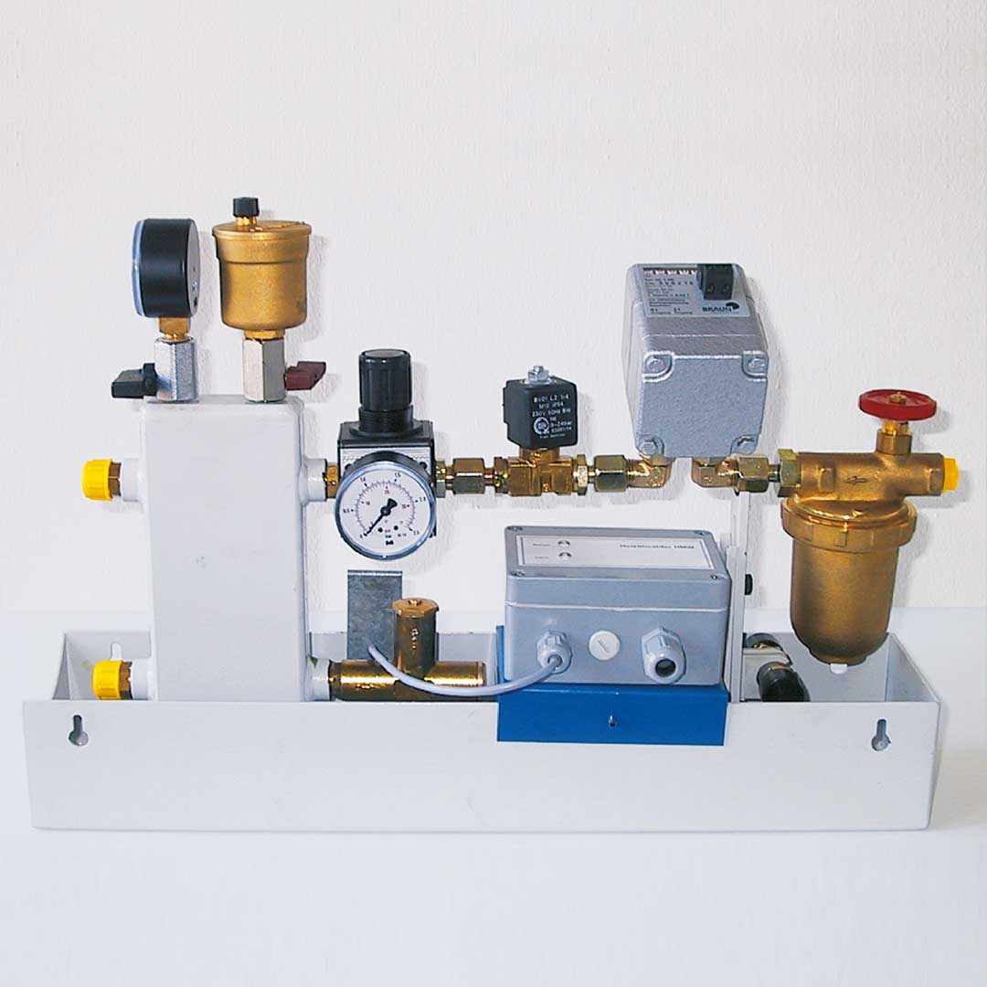
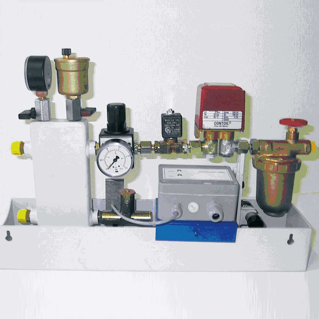
For single-pipe installation of the burner for supply pressure max. 10 bar, with pressure regulator set to 0.5 bar

Details and applications:

  • Filter with ball valve and filter cup (brass)
  • Adapter for oil meter
  • Solenoid valve for burner control system
  • Pressure regulator set fixed at secondary pressure 0.5 bar, system pressure max. 10 bar
  • Air-separation vessel with ball valve for manometer and
  • Automatic air vent for starting up
  • Pressure-equalising fitting, for increase in volume due to heating up
  • Completely fitted in oil pan for floor or wall fitting,
  • direction of flow may be left or right

Technical Data:

Diagram I with adapter for oil meter

with HZ 5 oil meter for max. 50 l/h

with VZO 8 oil meter for max. 135 l/h

Zubehör

Leckölmelder Typ LMW, Art.- Nr. 072 0705-1

Model Burner
throughput
max. bypass Filter
connection
Burner
connection
Item No. Dimensions Weight
Kg
Adapter for
oil meter
Max. oil
throughput
BA Diagram I 20 – 130 l/h 120 l/h G 3/8″ IG G 3/8″ 082 1204 465 x 105 x 315 5,6 HZ 5
VZO 8
40 l/h
135 l/h
BA Diagram III/2 150 – 400 l/h 360 l/h G 1/2″ IG G 1/2″ 082 1245 625 x 125 x 315 8,3 VZO 15 400 l/h

Air separation vessel

Size Tank Height Connection supply Burner Item No.
5 l DN 125 400 SRV 15 G 3/4″ 821210
17 l DN 200 500 SRV 15 G 3/4″ 821220
30 l DN 250 550 DN 20 G 1″ 821230
70 l DN 350 700 DN 25 G 1″ 821240

Scope of supply:

1 Vessel
2 Manual air vent
3 Manometer with ball valve
4 Safety valve without component test Set to 3 bar and sealed, adjustment possible

Optionen

10 Pressure switch
11 Solenoid valve
12 Oil meter
13 Filter
14 Pressure regulator
15 Double ball valve
16 Electrical end position switch for item
17 Ball valve in supply line
18 Automatic float air vent
19 Air vent with solenoid valve

Need additional infos? Please contact us

Jochen Twellaar

+49 (0) 721/95618-23

twellaar@hptechnik.com

Joachim Rau

+49(0) 721/95618-25

rau@hptechnik.com