Search
Close this search box.

Pressure-regulating valve with modulating kit

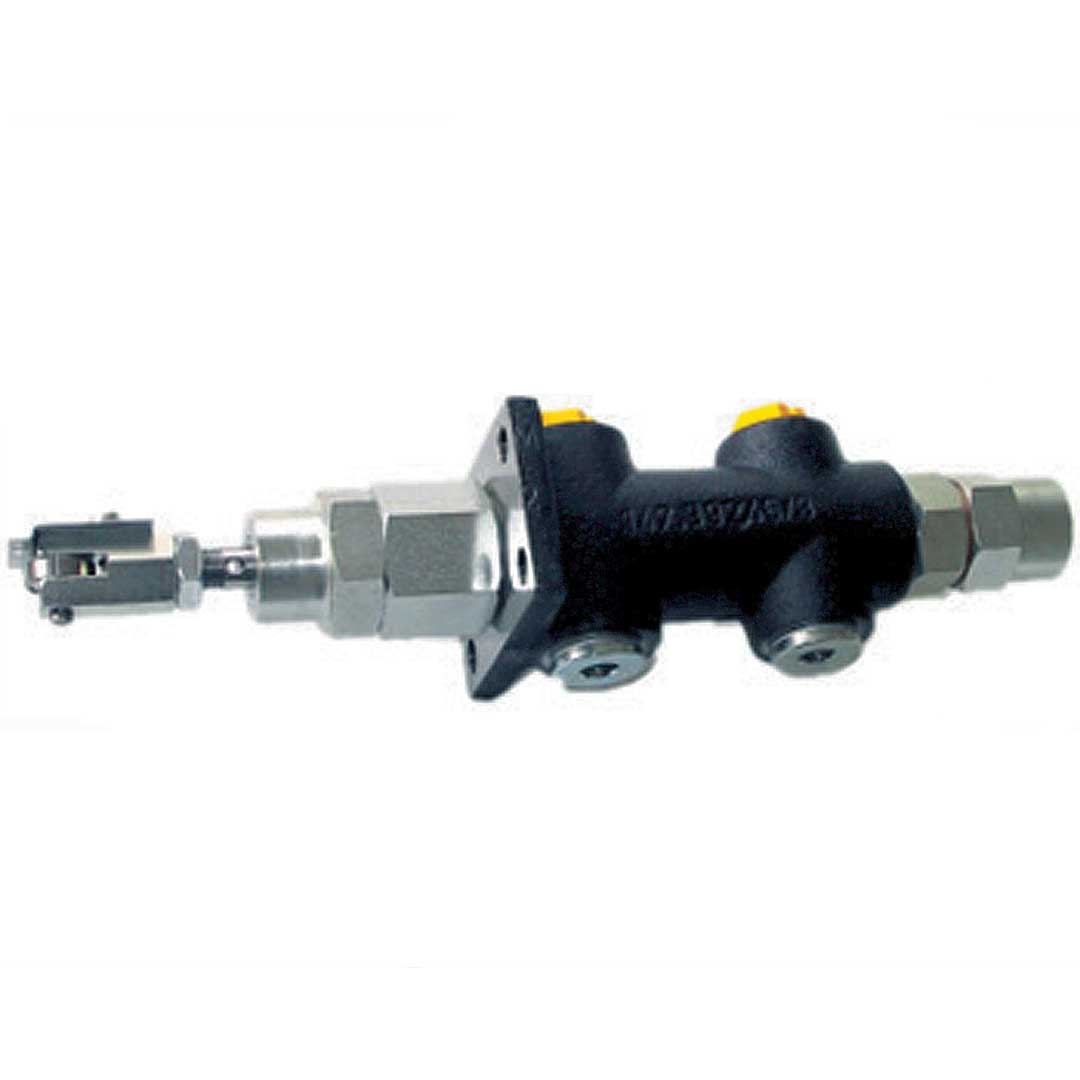
With the pressure regulating valve the oil quantity on the bypass of the burner is set, which is required to achieve the relevant nozzle or burner performance.

Material

Casing made of hydraulic cast iron (GGG40); piston, valve tip, spring of hardened steel

Details

Maximum temperature of fluid medium: 150 °C

Technical Data:

Model Possible
pressure stages for each model
Connection Flow range
l/h
Viscosity range

cSt

Item No. Weight (kg)
DRV 18 EL G 3/8″ 300-600 2,8 bis 480 025 0202 1,5
DRV 19 EL 2 = 2 – 18 bar G 3/4″ 1000-2000 2,8 bis 480 025 0206 3
DRV 21 S 3 = 6 – 25 bar G 3/8″ 300-600 2,8 bis 480 025 0210 1,5
DRV 22 S G 3/4″ 1000-2000 2,8 bis 480 025 0214 3

Pressure setting:

The return oil flows into the pressure chamber of the pressure regulating valve, situated between the piston (10) and valve cone (9). On the drain
side are situated the piston (10) and the spring (11). This spring is compressed more or less by the shaft that is supported in the guide bushing, depending on the burner performance. The greater the pressure on the spring, the greater the pressure in the bypass and therefore the nozzle consumption.

The basic setting is put on the regulating screw 4. Clockwise rotation corresponds to an increase in pressure, counterclockwise to a pressure reduction.
Positions:  4 Regulating screw | 9 Valve cone | 10 Piston | 11 Spring

Size table

Model a b1 b2 b3 b4 Flange dimensions
L B Hole pattern Ø
DRV 18 EL + 21 S 54 102 56 46 250 70 48 58 2 hole 8
DRV 19 EL + 22 S 63 119 76 46 300 70 70 54 x 54 4 hole 8

For installation, operation and maintenance, follow the operating instructions that come with each piece of equipment.

Need additional infos? Please contact us

Jochen Twellaar

+49 (0) 721/95618-23

twellaar@hptechnik.com

Joachim Rau

+49(0) 721/95618-25

rau@hptechnik.com