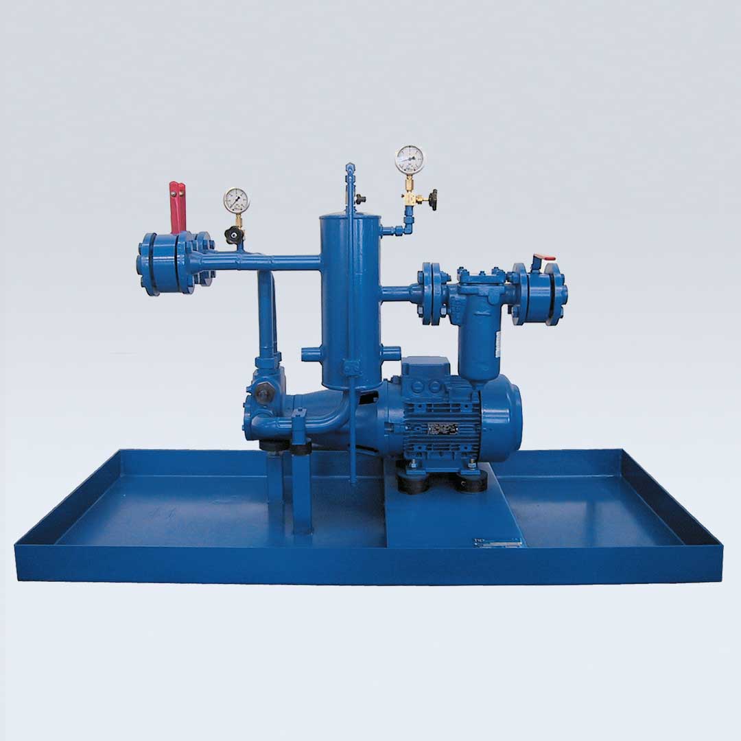
Fuel oil pressure unit with integrated bypass oil air separation for single-pipe oil supply for automatic oil burners to TRD 411 or TRD 604 and DIN 4755 sheet 2.
Technical Data:
Details and applications
Design “A” for supply pressure to max. 5 bar.
Medium: Fuel oil EL to DIN 51603
Viscosity: at 20 °C: max. 6 cST
pressure on shaft seal of pump: max. 5 bar on vacuum gauge (4)
The pump units are equipped with standard motors, flange size B3/B14 or B3/B5, 230/400 V, 50 Hz, 1400 RPM/, IP 55
Y-∆-cirquit with power supply must be specified with order. From 4 kW the motors are executed for 400/690 V, 50 Hz
Other voltage and frequencies can be supplied on request
Scope of supply:
Ball valve
Filter
Vacuum gauge with gauge valve
Vessel with manual ventilation
hp-Motor pump group consisting of:
hp-Internal gear pump with integrated overflow valve
and bypass connection, pump connector, coupling and
standard motor
Pressure gauge with gauge valve
Double ball valve for P + R
Complete assembled on an oil pan
Model key for determining order specifications
As most units of the MOG 19… series have to be engineered according to the burner power, we recommend fine-tuning with the manufacturer.
Accessories
Item
Label
Explanations
Item No.
15
PZ
Adapter for oil meter
16
Z
Oil meter
17
G/SE
Automatic float air vent
820212
18
DM
Pressure-regulator
Depending on design
19
LH
Leakage detector
0720705-1
20
M
Solenoid valve
Depending on design
21
E1
Optical filter indicator
820221
22
E2
Optical and electrical filter indicator
820222
Functional description: Design according to Scheme A (with supply pressure on T connection)
The pump (6) is supplied with oil via ball valve (1), filter (2), manometer (4), vessel (5) in single-pipe system, i.e. only the oil consumed by the burner flows here.
For manual ventilation, the supply pressure must be at least 1 and max. 5 bar. For automatic float air vent (accessories 17) the supply pressure must be max. 5 bar. A higher supply pressure must be reduced with pressure-regulator (accessories 18). Further accessories are adapters for oil meters (15), oil meter (16), solenoid valve (20), leakage detector (19) and filter indicator (21 + 22).
The pump (6) increases the supply pressure to the operating pressure that can be set on the overflow valve, that the pressure gauge (7) displays and supplies the pressurised oil to the burner via the ball valve (11). Return oil coming from the burner is fed back via the ball valve (11) to the vessel (5) and therefore the pump (6). If there is no oil consumption, the entire oil supplied by the pump is controlled via the overflow valve to the vessel (5) and therefore the inlet side of the pump (6).
Diagram
Scope of supply:
1 Ball valve PN 16
2 Filter PN 6
4 Vacuum gauge with gauge valve
5 Vessel with manual ventilation
6 hp-Motor pump group consisting of:
hp-Internal gear pump with integrated overflow valve and bypass connection, pump connector, coupling and standard motor
7 Pressure gauge with gauge valve
11 Double ball valve PN 40
14 Oil pan
Other designs (e.g. for suction operation or accessories) on request.
Accessories:
15 Adapter for oil meter installation
16 Oil meter
17 Automatic float air vent
18 Pressure regulator
19 Leakage detector
20 Solenoid valve
21 Optical filter indicator
22 Optical and electrical filter indicator
Overview Table
Unit model
Used pump model
Item No.
Operating pressure pmax in bar
Motor
power 1) kW
Vessel capacity in litres
Pipe connections* DIN flange
Discharge at 1400 RPM
including screws + seal
at 0 – 9 bar
at pmax
DIN 2633
T
DIN 2635
P
DIN 2633
R
MOG 1945 – A
VBGRP
620101
40
300
200
0,75
5
DN 15
DN 15
DN 15
MOG 1946 – A
VBGRM
620105
40
450
360
1,1
5
DN 15
DN 15
DN 15
MOG 1947 – A
VBGRG
620109
40
600
480
1,5
5
DN 15
DN 15
DN 15
MOG 1948 – A
VBHRP
620113
40
1000
600
2,2
5
DN 20
DN 20
DN 20
MOG 1949 – A
VBHRM
620117
40
1500
1000
3
5
DN 20
DN 20
DN 20
MOG 1950 – A
VBHRG
620121
40
2000
1400
4
5
DN 25
DN 25
DN 25
MOG 1951 – FL-A
VBHGRP
620125
40
3000
2000
5,5
5
DN 32
DN 32
DN 32
MOG 1951-1-FL-A
VBHGRPZ
620136
40
3700
2700
5,5
5,5
DN 32
DN 32
DN 32
MOG 1952 – FL-A
VBHGRM
620129
40
4500
3200
7,5
5
DN 40
DN 40
DN 40
MOG 1953 – FL-A
VBHGRG
620132
30
6000
4800
7,5
5
DN 40
DN 40
DN 40
* To ensure the pump is working properly, the pipes must be scaled according to the principles of fluid dynamics by calculation of line according to the local requirements.
The pump or device connection gives no indication of the relevant size of the pipe.
Durch die Nutzung unserer Website stimmen Sie der Verwendung von Cookies zur Verbesserung des Online-Erlebnisses zu. Mehr Informationen.
By using our website, you agree to the use of cookies to improve the online experience. More Information.