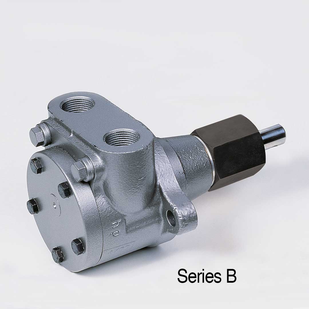
The industrial pumps of the B series are characterized by high operational reliability and their tried and tested design. The proven design ensures maintenance-free operation and a long service life. The pumps are ideal for pumping pure or slightly contaminated media such as paints, paraffins, synthetic resins, cutting oils, cooling lubricants, hydraulic oils, lubricating oils, motor oils, petroleum, solvents, bitumen, additives, fuels, heavy oils, heating oils, (bio) – Diesel, but also motor oils, thermal oils and vegetable oils. This makes the series suitable, for example, in dosing systems, machine tools, power plants or drying systems and much more.
Details
Areas of application
(Direction of rotation I = indirect – counterclockwise)
| hp-Internal gear pump Series B Sizes: |
Viscosity: 6 mm² sec-1 bei 20°C | Gear rotor size Ø |
Shaft Ø |
Threaded connection* pipe thread DIN ISO 228 |
Manometer connection* pipe thread DIN ISO 228 |
max. permitted pump speed (RPM) at l/D |
Net weight (kg) at l/D |
|||||||
| n = 1400 RPM Discharge l/h | n = 2800 RPM Discharge l/h | |||||||||||||
| at
9 bar |
bei
30 bar |
at
40 bar |
Item No.
l |
at
9 bar |
at
30 bar |
at
40 bar |
Item No.
l |
|||||||
| BP | 45 | 30 | 20 | 011/0002 | 90 | 60 | 50 | 013/0002 | 25 | 12 | 3/8“ | – | 3500 | 1,8 |
| BM | 80 | 60 | 50 | 011/0003 | 160 | 130 | 120 | 013/0003 | 25 | 12 | 3/8“ | – | 3500 | 1,8 |
| BG | 120 | 100 | 80 | 011/0004 | 240 | 200 | 190 | 013/0004 | 25 | 12 | 3/8“ | – | 3500 | 1,8 |
| BF | 160 | 140 | 120 | 011/0005 | 320 | 270 | 260 | 013/0005 | 25 | 12 | 3/8“ | – | 3500 | 1,8 |
| BG PP | 150 | 100 | 80 | 011/0052 | 300 | 240 | 210 | 013/0052 | 38 | 12 | 1/2“ | – | 3500 | 2,6 |
| BG PZ | 200 | 160 | 140 | 011/0053 | 400 | 310 | 280 | 013/0053 | 38 | 12 | 1/2“ | – | 3500 | 2,6 |
| BG P | 300 | 240 | 200 | 011/0019 | 600 | 520 | 480 | 013/0019 | 38 | 12 | 1/2“ | – | 3500 | 2,6 |
| BG MZ | – | – | – | – | 850 | 750 | 700 | 013/0068 | 38 | 12 | 1/2“ | – | 3500 | 2,6 |
| BG M | 450 | 390 | 360 | 011/0020 | 900 | 850 | 730 | 013/0020 | 38 | 12 | 1/2“ | – | 3500 | 2,6 |
| BG GZ | – | – | – | – | 1100 | 1000 | 870 | 013/0054 | 38 | 12 | 1/2“ | – | 3500 | 2,6 |
| BG G | 600 | 540 | 480 | 011/0021 | 1200 | 1080 | 960 | 013/0031 | 38 | 12 | 1/2“ | – | 2800 | 2,6 |
| BH P | 1000 | 700 | 600 | 011/0031 | – | – | – | – | 56 | 18 | 3/4“ | 1/4“ | 1700 | 6,4 |
| BH M | 1500 | 1200 | 1000 | 011/0032 | – | – | – | – | 56 | 18 | 3/4“ | 1/4“ | 1700 | 6,4 |
| BH G | 2000 | 1700 | 1400 | 011/0033 | – | – | – | – | 56 | 18 | 3/4“ | 1/4“ | 1700 | 6,4 |
| BHG P | 3000 | 2200 | 2000 | 011/0043 | – | – | – | – | 75 | 22 | 1 1/2“ | – | 1700 | 14,9 |
| BHG PZ | 3700 | 3000 | 2700 | 011/0080 | – | – | – | – | 75 | 22 | 1 1/2“ | – | 1700 | 14,9 |
| BHG M | 4500 | 3600 | 3200 | 011/0044 | – | – | – | – | 75 | 22 | 1 1/2“ | – | 1700 | 14,9 |
| BHG G | 6000 | 4800 | – | 011/0045 | – | – | – | – | 75 | 22 | 1 1/2“ | – | 1700 | 14,9 |
| BHG F | 6700 | 5800 | – | 011/0081 | – | – | – | – | 75 | 22 | 1 1/2“ | – | 1700 | 14,9 |
(Direction of rotation D = direct – clockwise)
| hp-hp-Internal gear pump Series B Sizes: |
Viscosity: 6 mm² sec-1 at 20°C | Gear rotor size Ø |
Shaft Ø |
Threaded connection* pipe thread DIN ISO 228 |
Manometer- connection* pipe thread DIN ISO 228 |
Heating power H1 in Watt 230 V, 50 Hz |
Breakaway torque of the pump (Nm) |
|||||||
| n = 1400 min-1 Discharge l/h | n = 2800 min-1 Discharge l/h | |||||||||||||
| bei
9 bar |
at
30 bar |
at
40 bar |
Item No.
D |
at
9 bar |
at
30 bar |
at
40 bar |
Item No.
D |
|||||||
| BP | 45 | 30 | 20 | 012/0002 | 90 | 60 | 50 | 014/0002 | 25 | 12 | 3/8“ | – | 100 | 1,2 |
| BM | 80 | 60 | 50 | 012/0003 | 160 | 130 | 120 | 014/0003 | 25 | 12 | 3/8“ | – | 100 | 1,2 |
| BG | 120 | 100 | 80 | 012/0004 | 240 | 200 | 190 | 014/0004 | 25 | 12 | 3/8“ | – | 100 | 1,2 |
| BF | 160 | 140 | 120 | 012/0005 | 320 | 270 | 260 | 014/0005 | 25 | 12 | 3/8“ | – | 100 | 1,2 |
| BG PP | 150 | 100 | 80 | 012/0052 | 300 | 240 | 210 | 014/0052 | 38 | 12 | 1/2“ | – | 100 | 1,6 |
| BG PZ | 200 | 160 | 140 | 012/0053 | 400 | 310 | 280 | 014/0053 | 38 | 12 | 1/2“ | – | 100 | 1,6 |
| BG P | 300 | 240 | 200 | 012/0019 | 600 | 520 | 480 | 014/0019 | 38 | 12 | 1/2“ | – | 100 | 1,6 |
| BG-MZ | – | – | – | – | 850 | 750 | 700 | 014/0068 | 38 | 12 | 1/2“ | – | 100 | 1,6 |
| BG M | 450 | 390 | 360 | 012/0020 | 900 | 850 | 730 | 014/0020 | 38 | 12 | 1/2“ | – | 100 | 1,6 |
| BG GZ | – | – | – | – | 1100 | 1000 | 870 | 014/0054 | 38 | 12 | 1/2“ | – | 100 | 1,6 |
| BG G | 600 | 540 | 480 | 012/0021 | 1200 | 1080 | 960 | 014/0031 | 38 | 12 | 1/2“ | – | 100 | 1,6 |
| BH P | 1000 | 700 | 600 | 012/0031 | – | – | – | – | 56 | 18 | 3/4“ | 1/4“ | 160 | 3,2 |
| BH M | 1500 | 1200 | 1000 | 012/0032 | – | – | – | – | 56 | 18 | 3/4“ | 1/4“ | 160 | 3,2 |
| BH G | 2000 | 1700 | 1400 | 012/0033 | – | – | – | – | 56 | 18 | 3/4“ | 1/4“ | 160 | 3,2 |
| BHG P | 3000 | 2200 | 2000 | 012/0043 | – | – | – | – | 75 | 22 | 1 1/2“ | – | 280 | 4,6 |
| BHG PZ | 3700 | 3000 | 2700 | 012/0080 | – | – | – | – | 75 | 22 | 1 1/2“ | – | 280 | 4 |
| BHG M | 4500 | 3600 | 3200 | 012/0044 | – | – | – | – | 75 | 22 | 1 1/2“ | – | 280 | 4,6 |
| BHG G | 6000 | 4800 | – | 012/0045 | – | – | – | – | 75 | 22 | 1 1/2“ | – | 280 | 4,6 |
| BHG F | 6700 | 5800 | – | 012/0081 | – | – | – | – | 75 | 22 | 1 1/2“ | – | 280 | 4,6 |
* To ensure the pump is working properly, the pipes must be scaled according to the principles of fluid dynamics by calculation of line according to the local requirements. The pump or device connection gives no indication of the relevant size of the pipe
| Gear rotor Size Ø |
Discharge l/h |
a1 | a2 | a3 | b1 | c1 | c2 | c3 | c4 | c5 | c6 | c7 | c8 | d1 | |
| 1400 min-1 | 2800 min-1 | ||||||||||||||
| 25 | 45 – 160 | 90 – 320 | 35,5 | 20 | 33 | 51 | 41,5 | 14 | 16 | 40 | 20 | 55,5 | 76 | 131,5 | 12 |
| 38 | 150 – 600 | 300 – 1200 | 43 | 26,5 | 38 | 70 | 55,5 | 14 | 16 | 40 | 20 | 69,5 | 76 | 145,5 | 12 |
| 56 | 1000 – 2000 | – | 48,5 | 38 | 45 | 96 | 71,5 | 15 | 18 | 79 | 27 | 86,5 | 124 | 210,5 | 18 |
| 75 | 3000 – 6700 | – | 64,5 | 83 | 70 | 115 | 129,5 | 18 | 25 | 65 | 37 | 147,5 | 127 | 274,5 | 22 |
| Gear rotor Size Ø |
Discharge l/h |
sw | e | d2 | d3 | e1 | f1 | f2 | f3 | f4 | g1 | h1 | h2 | h3 | |
| 1400 min-1 | 2800 min-1 | ||||||||||||||
| 25 | 45 – 160 | 90 – 320 | 27 | 31,2 | 54 | 80 | G 3/8″ | 71 | 16,5 | 38 | 92 | 43 | 11 | 13 | 13 |
| 38 | 150 – 600 | 300 – 1200 | 27 | 31,2 | 54 | 80 | G 1/2″ | 82 | 19 | 44 | 92 | 43 | 11 | 13 | 13 |
| 56 | 1000 – 2000 | – | 46 | 53,1 | 60 | 100 | G 3/4″ | 112 | 22,5 | 67 | 120 | 65 | 13 | 13 | 25 |
| 75 | 3000 – 6700 | – | 55 | 63,5 | 80 | 120 | G 1 1/2″ | 170 | 35 | 100 | 150 | 90 | 14,5 | 15 | – |
For gear rotor size 56 vacuum and manometer connection G 1/4″ on the front.
Need additional infos? Please contact us