Search
Close this search box.

Series PON, with integrated overflow valve, bypass and integrated filter

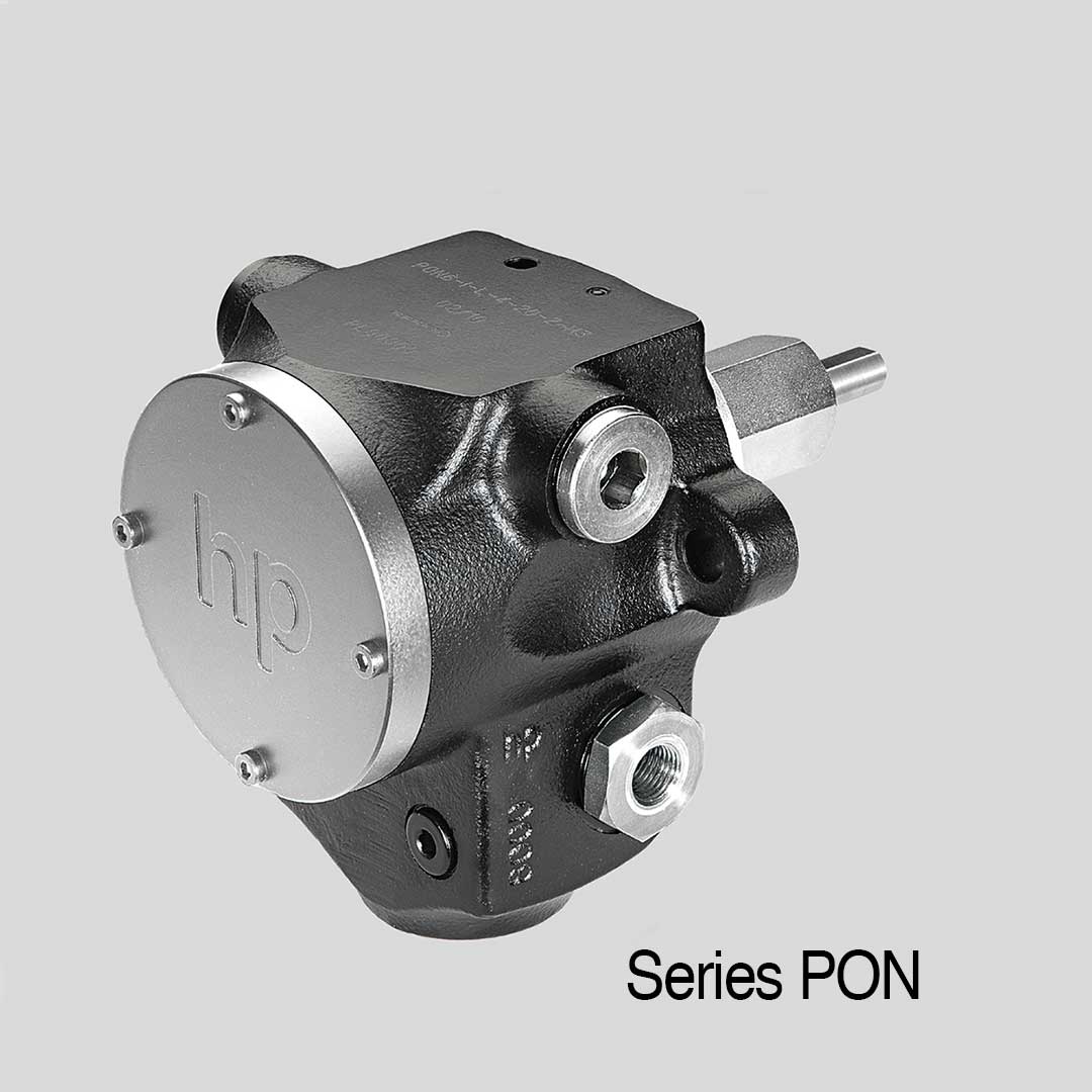
The PON industrial pump program is characterized by a robust and durable construction and can be used for a variety of applications. The pumps are ideal for pumping clean or slightly contaminated media such as bitumen, additives, fuels, heavy oils, but also vegetable oils. This makes the series suitable, for example, for dosing systems, machine tools, turbines or drying systems and much more that are used in machine tools, turbines or drying systems, for example. The pumps are preferably designed for direct installation on the burner and have a filter element integrated in the pump housing. This means that the operator can dispense with installing a filter in the suction line.

Technical Data:

Details

  • Self-priming
  • self-lubricating
  • practically non-pulsating, quiet-running,
  • practically maintenance-free, pressure-proof and vacuum-tight shaft seals
  • Discharge range: 45 to 1050 l/h
  • Operating pressure: 0 – 40 bar
  • Temperatures: up to 150°C (higher temperatures on request)
  • Direction of rotation
    • I = indirect – counterclockwise
    • D = direct – clockwise
  • Nozzle port
    • R = on the right hand side
    • L  = on the left hand side
      The direction of rotation can only be changed in the factory.
      Therefore please ensure that you state the desired direction of rotation and the direction of the nozzle port according to the dimension sheet when ordering.

  • Standard design of the pump for two-pipe installation, conversion to one-pipe operation can be done yourself (see operating and maintenance manual)
  • All hp-Industrial PON model pumps may be equipped with heating H3 and electrical standby and auxiliary heating without thermostat.

Areas of application

  • Construction
  • Agriculture
  • Marine / offshore

Technical Selection Chart

hp-Internal gear pumps of Series PON up to 40 bar

Size Discharge at 2800 RPM
Viscosity 5 cSt
Direction of rotation Nozzle
port
Item No. max. permitted
pump speed
(RPM)
Gear rotor
size Ø
Breakaway
torque
(Nm)

Net weight

 (kg)

9 bar 30 bar 40 bar I-L I-R D-L D-R
PON 3 90 60 50 D = direct –

clockwise

R 130601 130611 140601 140611 3500 25 1.2 5.0
PON 4 160 130 120 130602 130612 140602 140612 3500 25 1.2 5.0
PON 6 240 200 190 I = indirect –

counterclockwise

L 130603 130613 140603 140613 3500 25 1.2 5.0
PON 7 320 270 260 130604 130614 140604 140614 3500 25 1.2 5.0
Size Capacity at

9 bar (l/h)

Threaded connection Pressure stage
(bar)
Speed (RPM) Medium Accessories
Nozzle Suction side Bypass Manometer
PON 3 90 1/4″ 1/2″ 1/2″ 1/8″ 1 = 1 – 4 1 = 1400 RPM 0 = fuel oil EL + L H3 = heating for PON
PON 4 160 1/4″ 1/2″ 1/2″ 1/8″ 2 = 2 – 9 MGO / MDO E – single-pipe installation
PON 6 240 1/4″ 1/2″ 1/2″ 1/8″ 3 = 6 – 25 2 = 2800 RPM 5 = HFO
PON 7 320 1/4″ 1/2″ 1/2″ 1/8″ 4 = 15 – 40

Curves for Series PON

Scale drawings for Series PON

hp-Electric standby and auxiliary heating H3 for PON series hp-Oil burner pumps

For use of pumps with viscous medium, the use of H3 heating is provided by the manufacturer.

Need additional infos? Please contact us

Jochen Twellaar

+49 (0) 721/95618-23

twellaar@hptechnik.com

Joachim Rau

+49(0) 721/95618-25

rau@hptechnik.com