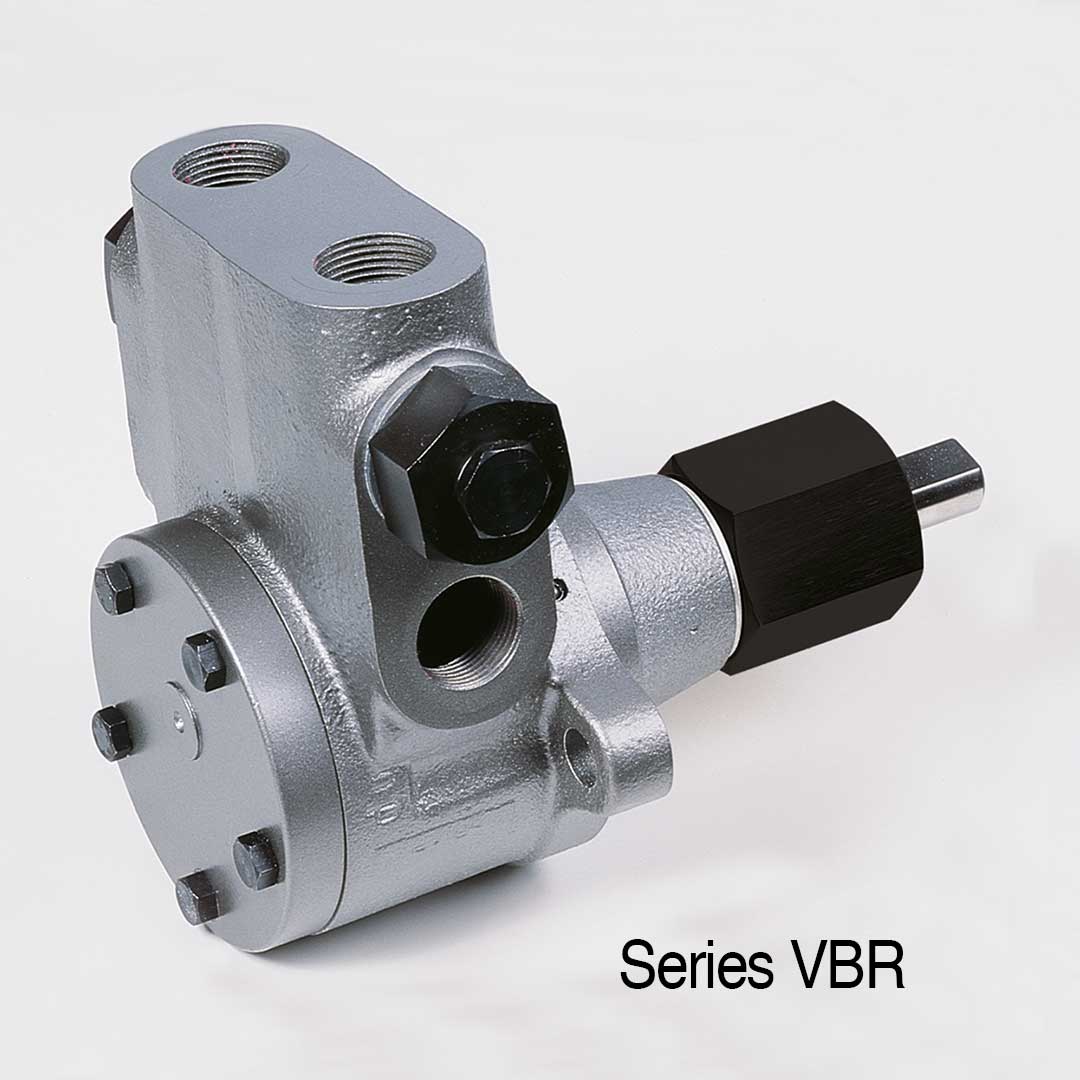
The VBR industrial pump program is characterized by a robust and durable construction and can be used for a variety of applications. The pumps are ideal for pumping clean or slightly contaminated media such as cutting oils, cooling lubricants, hydraulic oils, lubricating oils, motor oils, gear oils, kerosene, petroleum, glycol, heating oils, solvents, bitumen, additives, fuels, heavy oils, (bio) Diesel, but also thermal oils and vegetable oils. This makes the series suitable, for example, for dosing systems, machine tools, power plants or drying systems and much more. The industrial pumps of the VBR series have an integrated overflow valve and bypass, which ensures that a set maximum pressure is not exceeded. This relieves the pump in the direct bypass into the suction side.
Details
D = direct – clockwise
The direction of rotation can only be changed in the factory. Therefore, specify the desired direction of rotation as viewed from the pump shaft as per dimension sheet when ordering.
Areas of application
(direction of rotation I = indirect – counterclockwise)
| hp-Internal gear pump Series VBR Sizes: |
Viscosity: 6 mm² sec-1 at 20°C | Gear rotor size
Ø |
Shaft
Ø |
Threaded connection* pipe thread DIN ISO 228 |
Manometer connection* pipe thread DIN ISO 228 |
max.
permitted at l/D |
Net weight (kg) at l/D |
|||||||
| n = 1400 RPM Discharge l/h | n = 2800 RPM Discharge l/h | |||||||||||||
| at
9 bar |
at
30 bar |
at
40 bar |
Item No.
l |
at
9 bar |
at
30 bar |
at
40 bar |
Item No.
l |
|||||||
| VBR P | 45 | 30 | 20 | 011/0011 | 90 | 60 | 50 | 013/0011 | 25 | 12 | 3/8″ | – | 3500 | 2.9 |
| VBR M | 80 | 60 | 50 | 011/0012 | 160 | 130 | 120 | 013/0012 | 25 | 12 | 3/8″ | – | 3500 | 2.9 |
| VBR G | 120 | 100 | 80 | 011/0013 | 240 | 200 | 190 | 013/0013 | 25 | 12 | 3/8″ | – | 3500 | 2.9 |
| VBR F | 160 | 140 | 120 | 011/0014 | 320 | 270 | 260 | 013/0014 | 25 | 12 | 3/8″ | – | 3500 | 2.9 |
| VBGR PP | 150 | 100 | 80 | 011/0065 | 300 | 240 | 210 | 013/0040 | 38 | 12 | 1/2″ | – | 3500 | 3.7 |
| VBGR PZ | 200 | 160 | 140 | 011/0062 | 400 | 310 | 280 | 013/0041 | 38 | 12 | 1/2″ | – | 3500 | 3.7 |
| VBGR P | 300 | 240 | 200 | 011/0025 | 600 | 520 | 480 | 013/0023 | 38 | 12 | 1/2″ | – | 3500 | 3.7 |
| VBGR MZ | – | – | – | – | 850 | 750 | 700 | 013/0072 | 38 | 12 | 1/2″ | – | 3500 | 3.7 |
| VBGR M | 450 | 390 | 360 | 011/0026 | 900 | 850 | 730 | 013/0024 | 38 | 12 | 1/2″ | – | 3500 | 3.7 |
| VBGR GZ | – | – | – | – | 1100 | 1000 | 870 | 013/0042 | 38 | 12 | 1/2″ | – | 3500 | 3.7 |
| VBGR G | 600 | 540 | 480 | 011/0027 | 1200 | 1080 | 960 | 013/0043 | 38 | 12 | 1/2″ | – | 2800 | 3.7 |
| VBHR P | 1000 | 700 | 600 | 011/0037 | – | – | – | – | 56 | 18 | 3/4″ | – | 1700 | 8.4 |
| VBHR M | 1500 | 1200 | 1000 | 011/0038 | – | – | – | – | 56 | 18 | 3/4″ | – | 1700 | 8.4 |
| VBHR G | 2000 | 1700 | 1400 | 011/0039 | – | – | – | – | 56 | 18 | 3/4″ | – | 1700 | 8.4 |
| VBHGR P | 3000 | 2200 | 2000 | 011/0049 | – | – | – | – | 75 | 22 | 1″ 1) | 1/4″ | 1700 | 18.6 |
| VBHGR PZ | 3700 | 3000 | 2700 | 011/0090 | – | – | – | – | 75 | 22 | 1″ 1) | 1/4″ | 1700 | 18.6 |
| VBHGR M | 4500 | 3600 | 3200 | 011/0050 | – | – | – | – | 75 | 22 | 1″ 1) | 1/4″ | 1700 | 18.6 |
| VBHGR G | 6000 | 4800 | – | 011/0051 | – | – | – | – | 75 | 22 | 1″ 1) | 1/4″ | 1700 | 18.6 |
| VBHGR F | 6700 | 5800 | – | 011/0091 | – | – | – | – | 75 | 22 | 1″ 1) | 1/4″ | 1700 | 18.6 |
(direction of rotation D = direct – clockwise)
| hp-Internal gear pump Series VBR Sizes: |
Viscosity: 6 mm² sec-1 at 20°C | Gear rotor size
Ø |
Shaft
Ø |
Threaded connection* pipe thread DIN ISO 228 |
Manometer connection* pipe thread DIN ISO 228 |
Heating
power H1 in Watt |
Breakaway torque of the pump (Nm) |
|||||||
| n = 1400 RPM Discharge l/h | n = 2800 RPM Discharge l/h | |||||||||||||
| at
9 bar |
at
30 bar |
at
40 bar |
Item No.
D |
at
9 bar |
at
30 bar |
at
40 bar |
Item No.
D |
|||||||
| VBR P | 45 | 30 | 20 | 012/0011 | 90 | 60 | 50 | 014/0011 | 25 | 12 | 3/8″ | – | 100 | 1.2 |
| VBR M | 80 | 60 | 50 | 012/0012 | 160 | 130 | 120 | 014/0012 | 25 | 12 | 3/8″ | – | 100 | 1.2 |
| VBR G | 120 | 100 | 80 | 012/0013 | 240 | 200 | 190 | 014/0013 | 25 | 12 | 3/8″ | – | 100 | 1.2 |
| VBR F | 160 | 140 | 120 | 012/0014 | 320 | 270 | 260 | 014/0014 | 25 | 12 | 3/8″ | – | 100 | 1.2 |
| VBGR PP | 150 | 100 | 80 | 012/0065 | 300 | 240 | 210 | 014/0040 | 38 | 12 | 1/2″ | – | 100 | 1.6 |
| VBGR PZ | 200 | 160 | 140 | 012/0062 | 400 | 310 | 280 | 014/0041 | 38 | 12 | 1/2″ | – | 100 | 1.6 |
| VBGR P | 300 | 240 | 200 | 012/0025 | 600 | 520 | 480 | 014/0023 | 38 | 12 | 1/2″ | – | 100 | 1.6 |
| VBGR MZ | – | – | – | – | 850 | 750 | 700 | 014/0072 | 38 | 12 | 1/2″ | – | 100 | 1.6 |
| VBGR M | 450 | 390 | 360 | 012/0026 | 900 | 850 | 730 | 014/0024 | 38 | 12 | 1/2″ | – | 100 | 1.6 |
| VBGR GZ | – | – | – | – | 1100 | 1000 | 870 | 014/0042 | 38 | 12 | 1/2″ | – | 100 | 1.6 |
| VBGR G | 600 | 540 | 480 | 012/0027 | 1200 | 1080 | 960 | 014/0043 | 38 | 12 | 1/2″ | – | 100 | 1.6 |
| VBHR P | 1000 | 700 | 600 | 012/0037 | – | – | – | – | 56 | 18 | 3/4″ | 1/4″ | 160 | 3.2 |
| VBHR M | 1500 | 1200 | 1000 | 012/0038 | – | – | – | – | 56 | 18 | 3/4″ | 1/4″ | 160 | 3.2 |
| VBHR G | 2000 | 1700 | 1400 | 012/0039 | – | – | – | – | 56 | 18 | 3/4″ | 1/4″ | 160 | 3.2 |
| VBHGR P | 3000 | 2200 | 2000 | 012/0049 | – | – | – | – | 75 | 22 | 1″ 1) | 1/4″ | 280 | 4.6 |
| VBHGR PZ | 3700 | 3000 | 2700 | 012/0090 | – | – | – | – | 75 | 22 | 1″ 1) | 1/4″ | 280 | 4.6 |
| VBHGR M | 4500 | 3600 | 3200 | 012/0050 | – | – | – | – | 75 | 22 | 1″ 1) | 1/4″ | 280 | 4.6 |
| VBHGR G | 6000 | 4800 | – | 012/0051 | – | – | – | – | 75 | 22 | 1″ 1) | 1/4″ | 280 | 4.6 |
| VBHGR F | 6700 | 5800 | – | 012/0091 | – | – | – | – | 75 | 22 | 1″ 1) | 1/4″ | 280 | 4.6 |
* To ensure the pump is working properly, the pipes must be scaled according to the principles of fluid dynamics by calculation of line according to the local requirements.
The pump or device connection gives no indication of the relevant size of the pipe.
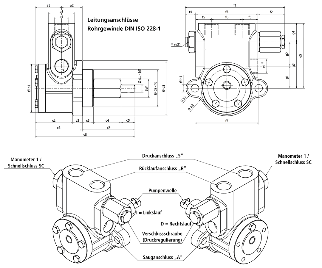
| Gear rotor size Ø |
Discharge l/h | a1 | a2 | a3 | b1 | c1 | c2 | c3 | c4 | c5 | c6 | c7 | c8 | |
| 1400 min-1 | 2800 min-1 | |||||||||||||
| 25 | 45 – 160 | 90 – 320 | 35,5 | 20 | 33 | 51 | 41,5 | 14 | 16 | 40 | 20 | 55,5 | 76 | 131,5 |
| 38 | 150 – 600 | 300 – 1200 | 39,5 | 30 | 38 | 70 | 55,5 | 14 | 16 | 40 | 20 | 69,5 | 76 | 145,5 |
| 56 | 1000 – 2000 | – | 48,5 | 38 | 45 | 96 | 71,5 | 15 | 18 | 79 | 27 | 86,5 | 124 | 210,5 |
| 75 | 3000 – 6700 | – | 62,5 | 85 | 70 | 115 | 129,5 | 18 | 25 | 65 | 37 | 147,5 | 127 | 274,5 |
| Gear rotor size Ø |
Discharge l/h | d1 | sw | e | d2 | d3 | e1 | *e2 | f1 | f2 | f3 | f4 | f5 | |
| 1400 min-1 | 2800 min-1 | |||||||||||||
| 25 | 45 – 160 | 90 – 320 | 12 | 27 | 31,2 | 54 | 80 | G 3/8“ | G 3/8“ | 144 | 38,5 | 90 | 15 | 26 |
| 38 | 150 – 600 | 300 – 1200 | 12 | 27 | 31,2 | 54 | 80 | G 1/2“ | G 3/8“ | 144 | 38,5 | 90 | 15 | 23 |
| 56 | 1000 – 2000 | – | 18 | 46 | 53 | 60 | 100 | G 3/4“ | G 3/8“ | 167,5 | 35 | 118 | 15 | 25,5 |
| 75 | 3000 – 6700 | – | 22 | 55 | 63,5 | 80 | 120 | G 1“ 1) | G 3/8“ | 200 | 28 | 150 | 21,5 | 35 |
| Gear rotor size Ø |
Discharge l/h | f6 | f7 | f8 | f9 | g1 | g2 | g3 | g4 | g5 | h1 | h2 | h3 | |
| 1400 min-1 | 2800 min-1 | |||||||||||||
| 25 | 45 – 160 | 90 – 320 | 38 | 92 | 140 | 18 | 30 | 33 | 63 | 27 | 90 | 11 | 13 | 13 |
| 38 | 150 – 600 | 300 – 1200 | 44 | 92 | 140 | 18 | 32 | 35 | 67 | 27 | 94 | 11 | 13 | 13 |
| 56 | 1000 – 2000 | – | 67 | 120 | 171 | 26,5 | 38 | 42 | 80 | 35 | 115 | 13 | 13 | 25 |
| 75 | 3000 – 6700 | – | 80 | 150 | 218 | 32 | 18 | 62 | 80 | 40 | 120 | 14,5 | 15 | – |
VBGHR model with G 1/4″ manometer connection on the front
1) For pinion size 75 = 3000 to 6700 l/h the side suction connection is G 1 1/2″.
Need additional infos? Please contact us