Search
Close this search box.

Single-pumping unit Series MOG

TÜV Rheinland
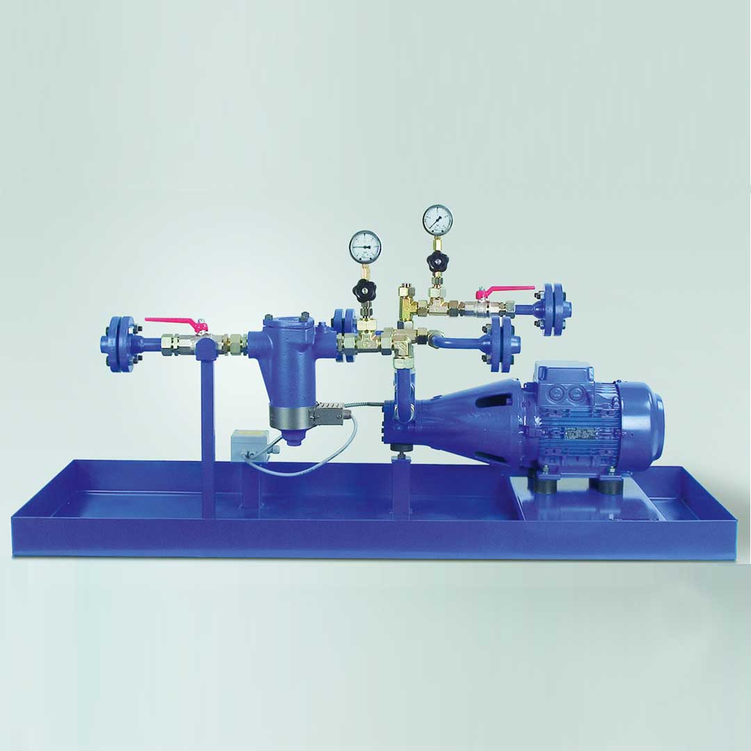
hp-Single pumping unit is screwed-on or flanged design as feed or pressure modules for oil supply to TRD 411 or TRD 604 and DIN 4755-2 must be constructed, tested, registered and labelled to test standard DIN EN 12514-1. For fuel oil supply diagram, see page 101.

Details & Applications

Viscosity range: Motor capacities of the units are designed for:

  • Viscosities up to 80 cSt. for units for fuel oil EL, L
  • Viscosities up to 150 cSt. for units for fuel oil M, S + ES
    Please ask for any differing conditions.

max. permitted underpressure: Measured on the vacuum gauge item 3 ≤ -0.6 bar
max. system pressure: 5 bar

Technical Data:

Scheme I for MOG 50, MOG 51, MOG 53 and MOG 55 series (without bypass line)

Schema I für Baureihen MOG 50, MOG 51, MOG 53 und MOG 55 (ohne Rücklaufleitung)

Scheme II for MOG 52 and MOG 54 series (with bypass line)

Schema II für Baureihen MOG 52 und MOG 54 (mit Rücklaufleitung)

Item no. for accessories: For “RV” and “DK” accessories, see data table. For “A” filter + pump with electrical auxiliary heating, see data table. Accessories E1, E2, L and S see page 96.

* List key letters one after the other
1) When used as feed pump aggregate for fuel oil supply to DIN 4736, the max. operating pressure of 6 bar must not be exceeded.

Note: In the place where it is fitted, as a “lower limiter” an electrical pressure monitor must be provided as a pipe break check. This condition is met by selecting the “S” accessory.

Model key for determining order specifications

Series size Size Accessories*
50 = Feed pump aggregate 9 bar and 6 bar, 1) fuel oil EL + L, kerosene
51 = Feed pump aggregate 9 bar, fuel oil M, S + ES, mineral tar oil
52 = Pressure aggregate 30 bar,
fuel oil EL + L + kerosene
53 = Pressure aggregate 30 bar, fuel oil M, S, + ES
54 = Pressure aggregate 40 bar, fuel oil EL + L
55 = Pressure aggregate 40 bar, fuel oil M, S + ES
Other designs on request
Discharge see
data tables
FL = flanged design A = Filter and pump with electrical auxilary heating
with connection boxE1 = With optical filter indicator

E2 = With optical and electrical filter indicator

LH = Oil pan equipped with leakage detection

RV = Nonreturn valve, only for scheme II
DK = Double ball valve, only with MOG 52 and MOG 54

S1) = With electrical pressure switch for monitoring
the pressure line (pipe burst check)

DT = Pressure transmitter

Feed pump aggregate according to Scheme I without bypass connection for fuel oil EL, L - max. pressure 9 bar

Unit model
Device connections Discharge at 1400 RPM
at 0 – 9 bar
used Item No. Unit
dimensions
L x B [mm]
max. pressure [bar]
screw-fitted flanged Pump model
Motor
power [kW]
screw-fitted
design
flanged
design
MOG 5001 Pipe-Ø 12 45 VB P 0,18 510101 700×270 designed for
max. pressure
of 9 barto
DIN EN 12514-1
max. working pressure of
6 bar.
MOG 5002 Pipe-Ø 12 80 VB M 0,18 510102 700×270
MOG 5003 Pipe-Ø 12 120 VB G 0,18 510103 700×270
MOG 5004 Pipe-Ø 12 160 VB F 0,18 510104 700×270
MOG 5005 Pipe-Ø 18 DN 15 300 VBG P 0,18 510105 510205 840×270
MOG 5006 Pipe-Ø 18 DN 15 450 VBG M 0,37 510106 510206 840×270
MOG 5007 Pipe-Ø 18 DN 15 600 VBG G 0,37 510107 510207 840×270
MOG 5008 Pipe-Ø 22 DN 25 1000 VBH P 0,75 510108 510208 1050×360
MOG 5009 Pipe-Ø 22 DN 25 1500 VBH M 0,75 510109 510209 1050×360
MOG 5010 Pipe-Ø 22 DN 25 2000 VBH G 1,1 510110 510210 1050×360
MOG 5011 DN 32 3000 VBHG P 1,5 510211 1400×500
MOG 5011-1 DN 32 3700 VBHG PZ 1,5 510214 1400×500
MOG 5012 DN 32 4500 VBHG M 2,2 510212 1400×500
MOG 5013 DN 40 6000 VBHG G 3,0 510213 1400×500

Feed pump aggregate according to Scheme I without bypass connection for fuel oil M, S + ES - max. pressure 9 bar

Unit model Device connections Discharge at
1400 RPM
at 0 – 9 bar
used Iem No. Unit
dimensions
L x B [mm]
SStationary and
auxiliary
heating
accessory “A”
max. pressure
[bar]
screw-fitted flanged Pump model Motor
power [kW]
screw-fitted
design
flanged
design
MOG 5101 Pipe-Ø 12 45 VB P 0,18 510114 700×270 bWhen
used
for
fuel oil S + ES
urgently
recommended.
designed for
max. pressure
of 9 bar
MOG 5102 Pipe-Ø 12 80 VB M 0,18 510115 700×270
MOG 5103 Pipe-Ø 12 120 VB G 0,18 510116 700×270
MOG 5104 Pipe-Ø 12 160 VB F 0,18 510117 700×270
MOG 5105 Pipe-Ø 18 DN 15 300 VBG P 0,18 510118 510218 840×270
MOG 5106 Pipe-Ø 18 DN 15 450 VBG M 0,37 510119 510219 840×270
MOG 5107 Pipe-Ø 18 DN 15 600 VBG G 0,37 510120 510220 840×270
MOG 5108 Pipe-Ø 22 DN 25 1000 VBH P 0,75 510121 510221 1050×360
MOG 5109 Pipe-Ø 22 DN 25 1500 VBH M 0,75 510122 510222 1050×360
MOG 5110 Pipe-Ø 22 DN 25 2000 VBH G 1,1 510123 510223 1050×360
MOG 5111 DN 32 3000 VBHG P 1,5 510224 1400×500
MOG 5111-1 DN 32 3700 VBHG PZ 1,5 510227 1400×500
MOG 5112 DN 32 4500 VBHG M 2,2 510225 1400×500
MOG 5113 DN 40 6000 VBHG G 3,0 510226 1400×500

Pressure aggregate according to Scheme I without bypass connection for fuel oil M, S + ES - max. pressure 30 bar

Unit model Device connections* Discharge at
1400 RPM
used Item No.: Unit
dimensions
L x B [mm]
Stationary and
auxiliary heating
accessory “A”
max.
pressure
[bar]
screw-fitted flanged at
0 – 9 bar
at pmax Pump model Motor
power [kW]
gscrew-fitted
design
flanged
design
MOG 5305 Rohr-Ø 18 DN 15 300 240 VBG P 0,75 510130 510230 840×270 Urgently
recommended
when used
for fuel
oil S + ES
desiged for
max. pressure
of 30 bar
von 30 bar
MOG 5306 Rohr-Ø 18 DN 15 450 390 VBG M 1,1 510131 510231 840×270
MOG 5307 Rohr-Ø 18 DN 15 600 540 VBG G 1,5 510132 510232 840×270
MOG 5308 Rohr-Ø 22 DN 25 1000 700 VBH P 2,2 510133 510233 1300×400
MOG 5309 Rorh-Ø 22 DN 25 1500 1200 VBH M 3,0 510134 510234 1300×400
MOG 5310 Rohr-Ø 22 DN 25 2000 1700 VBH G 4,0 510135 510235 1300×400
MOG 5311 DN 32 3000 2200 VBHG P 5,5 510236 1400×500
MOG 5311-1 DN 32 3700 3000 VBHG PZ 5,5 510239 1400×500
MOG 5312 DN 32 4500 3600 VBHG M 7,5 510237 1400×500
MOG 5313 DN 40 6000 4800 VBHG G 7,5 510238 1400×500

Pressure aggregate according to Scheme I without bypass connection for fuel oil M, S + ES - max. pressure 40 bar

Unit model Device connections* Discharge at
1400 RPM
used Item No.: Unit
dimensions
L x B [mm]
Stationary and
auxiliary heating
accessory “A”
max.
pressure
[bar]
screw-fitted flanged at
0 – 9 bar
at pmax Pump model Motor
power [kW]
gscrew-fitted
design
flanged
design
MOG 5505 Rohr-Ø 18 DN 15 300 200 VBG P 0,75 510140 510240 840×270 When
used
for
fuel oil S + ES
urgently
recommended.
designed for
max. pressure
of 40 bar
MOG 5506 Rohr-Ø 18 DN 15 450 360 VBG M 1,5 510141 510241 840×270
MOG 5507 Rohr-Ø 18 DN 15 600 480 VBG G 2,2 510142 510242 840×270
MOG 5508 Rorh-Ø 22 DN 25 1000 600 VBH P 3,0 510143 510243 1300×400
MOG 5509 Rohr-Ø 22 DN 25 1500 1000 VBH M 4,0 510144 510244 1300×400
MOG 5510 Rorh-Ø 22 DN 25 2000 1400 VBH G 5,5 510145 510245 1300×400
MOG 5511 DN 32 3000 2000 VBHG P 7,5 510246 1400×500
MOG 5511-1 DN 32 3700 2700 VBHG PZ 7,5 510248 1400×500
MOG 5512 DN 32 4500 3200 VBHG M 7,5 510247 1400×500

Pressure aggregate according to Scheme II with bypass connection for fuel oil EL + L - max. pressure 30 bar

Unit model Device connections* Discharge at

1400 RPM

used Item No.: Unit
dimensions
max. pressure [bar]
screw-fitted flanged at
0 – 9 bar
at pmax Pump model Motor
power [kW]
screw-fitted
design
flanged
design
L x B [mm]
MOG 5201 Pipe-Ø 12 45 30 VBR P 0,18 510148 700×270 designed for

max. pressure

of 30 bar

MOG 5202 Pipe-Ø 12 80 60 VBR M 0,18 510149 700×270
MOG 5203 Pipe-Ø 12 120 100 VBR G 0,18 510150 700×270
MOG 5204 Pipe-Ø 12 160 140 VBR F 0,37 510151 700×270
MOG 5205 Pipe-Ø 18 DN 15 300 240 VBGR P 0,75 510152 510252 1050×360
MOG 5206 Pipe-Ø 18 DN 15 450 390 VBGR M 0,75 510153 510253 1050×360
MOG 5207 Pipe-Ø 18 DN 15 600 540 VBGR G 1,1 510154 510254 1050×360
MOG 5208 Pipe-Ø 22 DN 25 1000 700 VBHR P 1,5 510155 510255 1400×500
MOG 5209 Rorh-Ø 22 DN 25 1500 1200 VBHR M 2,2 510156 510256 1400×500
MOG 5210 Pipe-Ø 22 DN 25 2000 1700 VBHR G 3,0 510157 510257 1400×500
MOG 5211 DN 32 3000 2200 VBHGR P 4,0 510258 1600×500
MOG 5211-1 DN 32 3700 3000 VBHGR PZ 4,0 510261 1600×500
MOG 5212 DN 32 4500 3600 VBHGR M 5,5 510259 1600×500
MOG 5213 DN 40 6000 4800 VBHGR G 7,5 510260 1600×500

Pressure aggregate according to Scheme II with bypass connection for fuel oil EL + L - max. pressure 40 bar

Unit model Device connections* Discharge at

1400 RPM

used Item No.: Unit
dimensions
max. pressure [bar]
screw-fitted flanged at
0 – 9 bar
at pmax Pump model Motor
power [kW]
screw-fitted
design
flanged
design
L x B [mm]
MOG 5405 Pipe-Ø 18 DN 15 300 200 VBGR P 0,75 510165 510265 1050×360 designed for

of 40 bar

MOG 5406 Pipe-Ø 18 DN 15 450 360 VBGR M 1,1 510166 510266 1050×360
MOG 5407 Pipe-Ø 18 DN 15 600 480 VBGR G 1,5 510167 510267 1050×360
MOG 5408 Rorh-Ø 22 DN 25 1000 600 VBHR P 2,2 510168 510268 1400×500
MOG 5409 Pipe-Ø 22 DN 25 1500 1000 VBHR M 3,0 510169 510269 1400×500
MOG 5410 Rorh-Ø 22 DN 25 2000 1400 VBHR G 4,0 510170 510270 1400×500
MOG 5411 DN 32 3000 2200 VBHGR P 5,5 510271 1600×500
MOG 5411-1 DN 32 3700 2700 VBHGR PZ 5,5 510282 1400×500
MOG 5412 DN 32 4500 3200 VBHGR M 7,5 510272 1600×500

Scope of supply:

  1. hp-Motor pump group
  2. Single filter
  3. Vacuum gauge
  4. Pressure gauge
  5. Ball valve
  6. Oil pan

Optional accessories:

7. Leakage detector LH
8. Electrical pressure switch or pressure transmitter S / DT
9. Nonreturn valve (only for Scheme II), not used for
selection of accessories 10 RV
10. Double ball valve (only for Scheme II) DK

Item no. for accessories

A = Filter and pump with electrical auxiliary heating and connection box
E1 = with optical filter indicator 820221
E2 = with optical and electrical filter indicator 820222
LH = Oil pan fitted with leakage detector, without electrical wiring 0720705-1
S = with attached electrical pressure switch for monitoring pressure line Typ FF4 820290
(Pipe break check) without electrical wiring Typ DSB 820292
DT = Pressure transmitter 720695

* To ensure the pump is working properly, the pipes must be scaled according to the principles of fluid dynamics by calculation of line according to the local requirements. The pump or device connection gives no indication of the relevant size of the pipe.

Motors used to IE 3, IP 55, 230/400 V from 4 kW 400/690 V, 50 Hz can also be used in 60 Hz operation – other voltages, frequencies and protection types on request.
Specifications for dimensions are guidelines, we will send the actual setup diagram when the order in placed.
Other designs or accessories (e.g. double filters, solenoid valves etc.) can be planned and provided on request.

Need additional infos? Please contact us

Jochen Twellaar

+49 (0) 721/95618-23

twellaar@hptechnik.com

Joachim Rau

+49(0) 721/95618-25

rau@hptechnik.com