hp-Twin-pumping unit in screwed-on or flanged design as feed or pressure units for oil supply to TRD 411 or TRD 604 and DIN 4755-2 must be constructed, tested, registered and labelled to test standard DIN EN 12514-1!
Viscosity range: Motor capacities of the units are designed for:
max. permitted underpressure: Measured on the manometer item 3 ≤ -0.6 bar
max. system pressure: 5 bar
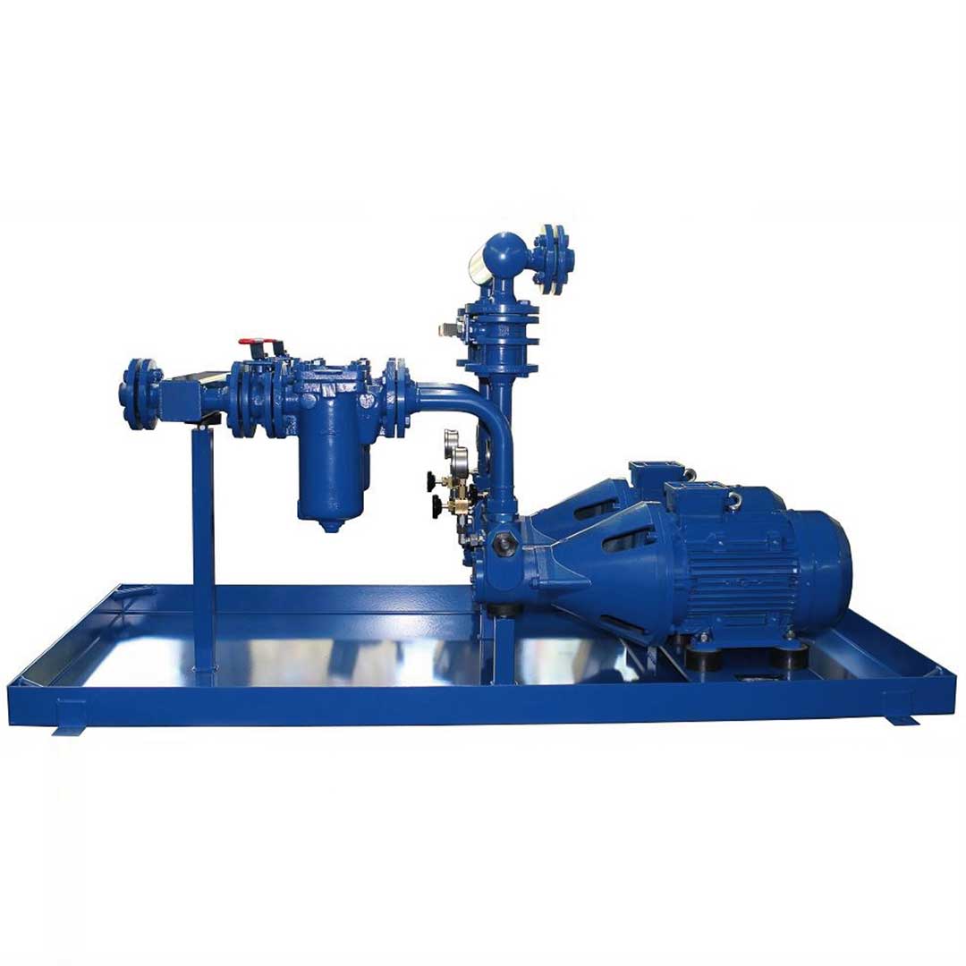
Scheme I
for BIK 50, BIK 51 and BIK 55 series (without bypass line)
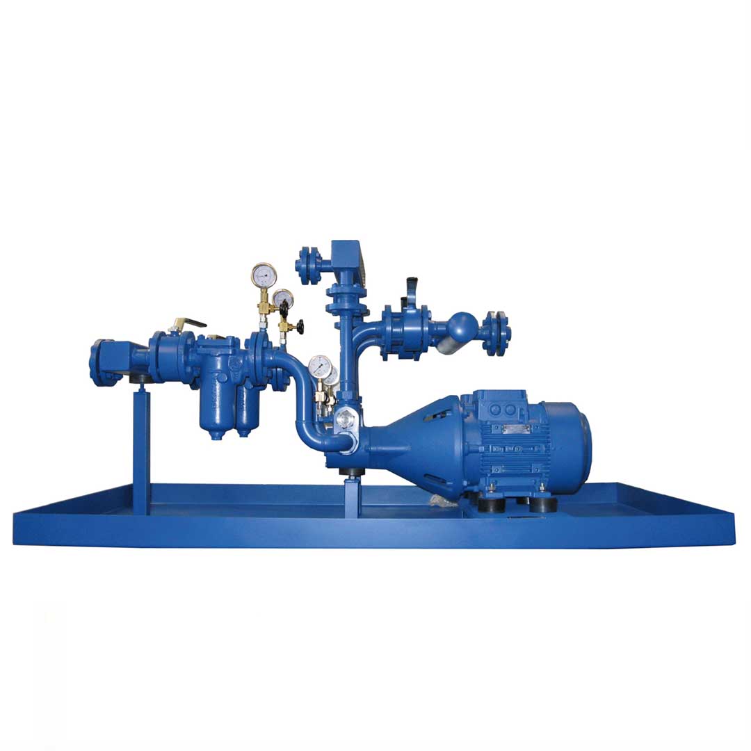
Scheme III
for BIK 52 and BIK 54 series (with bypass line)
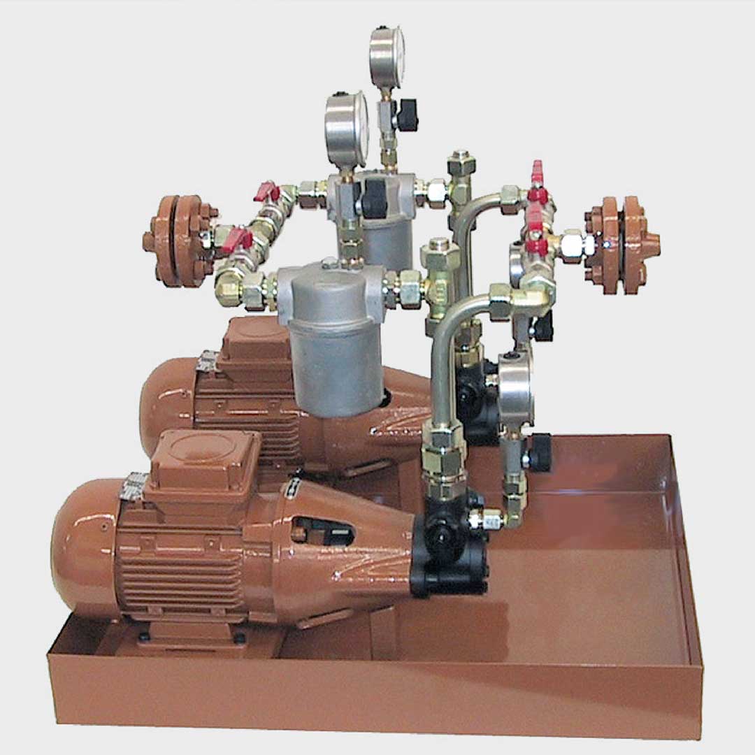
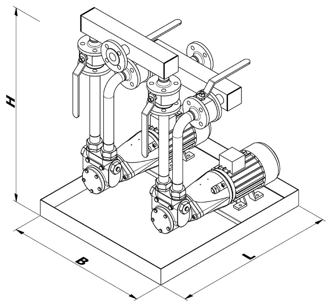
1 hp-Motor pump group
2 Single filter
3 Vacuum gauge
4 Pressure gauge
5 Ball valve
6 Oil pan
9 Nonreturn valve
5a Ball valve pressure side
(from 3000 l/h – scope of supply)
7 Leakage detector LH
8 Electrical pressure switch or pressure transmitter S / DT
| Serie | Size | Accessories* | |
| 50 = Feeder unit 9 bar and 6 bar, 1) heating oil EL + L, kerosene 51 = Feeder unit 9 bar, heating oil M, S + ES, mineral tar oil 52 = Pressure unit 30 bar, heating oil EL + L + kerosene 54 = Pressure unit 40 bar, heating oil EL + L 55 = Pressure unit 40 bar, heating oil M, S + ESOther designs on request |
Discharge see data tables
|
FL = flanged design
|
A = Filter and pump with electrical auxiliary heating with connecting boxEF = with 2 single filters DF = with changeable double filter E1 = with optical filter detection E2 = with optical and electrical filter detection (E1 and E2) LH = Oil pan equipped with oil leakage detection
|
Item no. for accessories: Accessories “A” filter + pump with electrical
auxiliary heating, accessories E1, E2, L and S see page 96.
* List key letters one after the other
1) When used as feed pump aggregate for fuel oil supply to DIN 4736, the max. operating pressure of 6 bar must not be exceeded.
Note: In the place where it is fitted, as a “lower limiter” an electrical pressure monitor must be provided as a pipe break check. This condition is met by selecting the “S” accessory.
Feed pump aggregate according to Scheme I without bypass for fuel oil EL, L - max. pressure 9 bar
| Unit model | Device connections* | Discharge at 1400 RPM at 0 – 9 bar |
used | Item No.: | Unit dimensions L x B [mm] |
max. pressure [bar] | |||
| screw-fitted | flanged | Pump model | Motor power [kW] |
screw-fitted design |
flanged design |
||||
| BIK 5001 | Pipe-Ø 12 | – | 45 | VB P | 0,18 | 520046 | – | 600×500 |
flanged |
| BIK 5002 | Pipe-Ø 12 | – | 80 | VB M | 0,18 | 520047 | – | 600×500 | |
| BIK 5003 | Pipe-Ø 12 | – | 120 | VB G | 0,18 | 520048 | – | 600×500 | |
| BIK 5004 | Pipe-Ø 12 | – | 160 | VB F | 0,18 | 520049 | – | ||
| BIK 5005 | Pipe-Ø 18 | DN 15 | 300 | VBG P | 0,18 | 520050 | 520051 | 600×500 | |
| BIK 5006 | Pipe-Ø 18 | DN 15 | 450 | VBG M | 0,37 | 520056 | 520052 | 600×500 | |
| BIK 5007 | Pipe-Ø 18 | DN 15 | 600 | VBG G | 0,37 | 520057 | 520053 | 600×500 | |
| BIK 5008 | Pipe-Ø 22 | DN 25 | 1000 | VBH P | 0,75 | 520058 | 520054 | 800×700 | |
| BIK 5009 | Pipe-Ø 22 | DN 25 | 1500 | VBH M | 0,75 | 520059 | 520055 | 800×700 | |
| BIK 5010 | Pipe-Ø 22 | DN 25 | 2000 | VBH G | 1,1 | 520060 | 520064 | 800×700 | |
| BIK 5011 | – | DN 32 | 3000 | VBHG P | 1,5 | – | 520061 | 800×700 | |
| BIK 5011-1 | – | DN 32 | 3700 | VBHG PZ | 1,5 | – | 520065 | 800×700 | |
| BIK 5012 | – | DN 32 | 4500 | VBHG M | 2,2 | – | 520062 | 800×700 | |
| BIK 5013 | – | DN 40 | 6000 | VBHG G | 3,0 | – | 520063 | 800×700 | |
| Unit model | Device connections* | Discharge at 1400 RPM at 0 – 9 bar |
used | Item No.: | Unit dimensions L x B [mm] |
Stationary and auxiliary heating accessory “A” |
max. pressure [bar] | |||
| screw-fitted | flanged | Pump model | Motor power [kW] |
screw-fitted design |
flanged design |
|||||
| BIK 5101 | Pipe-Ø 12 | – | 45 | VB P | 0,18 | 520111 | – | 600×500 | When used for fuel oil S + ES urgently recommended. See page 96 |
designed for |
| BIK 5102 | Pipe-Ø 12 | – | 80 | VB M | 0,18 | 520112 | – | 600×500 | ||
| BIK 5103 | Pipe-Ø 12 | – | 120 | VB G | 0,18 | 520113 | – | 600×500 | ||
| BIK 5104 | Pipe-Ø 12 | – | 160 | VB F | 0,18 | 520114 | – | |||
| BIK 5105 | Pipe-Ø 18 | DN 15 | 300 | VBG P | 0,18 | 520115 | 520330 | 600×500 | ||
| BIK 5106 | Pipe-Ø 18 | DN 15 | 450 | VBG M | 0,37 | 520116 | 520331 | 600×500 | ||
| BIK 5107 | Pipe-Ø 18 | DN 15 | 600 | VBG G | 0,37 | 520117 | 520332 | 600×500 | ||
| BIK 5108 | Pipe-Ø 22 | DN 25 | 1000 | VBH P | 0,75 | 520118 | 520333 | 800×700 | ||
| BIK 5109 | Pipe-Ø 22 | DN 25 | 1500 | VBH M | 0,75 | 520119 | 520334 | 800×700 | ||
| BIK 5110 | Pipe-Ø 22 | DN 25 | 2000 | VBH G | 1,1 | 520120 | 520335 | 800×700 | ||
| BIK 5111 | – | DN 32 | 3000 | VBHG P | 1,5 | – | 520336 | 800×700 | ||
| BIK 5111-1 | – | DN 32 | 3700 | VBHG PZ | 1,5 | – | 520339 | 800×700 | ||
| BIK 5112 | – | DN 32 | 4500 | VBHG M | 2,2 | – | 520337 | 800×700 | ||
| BIK 5113 | – | DN 40 | 6000 | VBHG G | 3,0 | – | 520338 | 800×700 | ||
* To ensure the pump is working properly, the pipes must be scaled according to the principles of fluid dynamics by calculation of line according to the local requirements. The pump or device connection gives no indication of the relevant size of the pipe.
Motors used to IE 3, IP 55, 230/400 V from 4 kW 400/690 V, 50 Hz can also be used in 60 Hz operation – other voltages, frequencies and protection types on request.
Specifications for dimensions are guidelines, we will send the actual setup diagram when the order in placed.
Other designs or accessories (e.g. double filters, solenoid valves etc.) can be planned and provided on request.
| Unit model | Device connections* | Discharge at 1400 RPM |
used | Item No.: | Unit dimensions L x B [mm] |
max. pressure [bar] |
||||
| screw-fitted | flanged | at 0 – 9 bar |
at pmax | Pump model | Motor power [kW] |
screw-fitted design |
flanged design |
|||
| BIK 5201 | Pipe-Ø 12 | – | 45 | 30 | VBR P | 0,18 | 520141 | – | 600×500 | adesigned for max. pressure of 30 bar |
| BIK 5202 | Pipe-Ø 12 | – | 80 | 60 | VBR M | 0,18 | 520142 | – | 600×500 | |
| BIK 5203 | Pipe-Ø 12 | – | 120 | 100 | VBR G | 0,18 | 520143 | – | 600×500 | |
| BIK 5204 | Pipe-Ø 12 | – | 160 | 140 | VBR F | 0,37 | 520144 | – | 600×500 | |
| BIK 5205 | Pipe-Ø 18 | DN 15 | 300 | 240 | VBGR P | 0,75 | 520145 | 520390 | 600×500 | |
| BIK 5206 | Pipe-Ø 18 | DN 15 | 450 | 390 | VBGR M | 0,75 | 520146 | 520391 | 600×500 | |
| BIK 5207 | Pipe-Ø 18 | DN 15 | 600 | 540 | VBGR G | 1,1 | 520147 | 520392 | 600×500 | |
| BIK 5208 | Pipe-Ø 22 | DN 25 | 1000 | 700 | VBHR P | 1,5 | 520148 | 520393 | 800×700 | |
| BIK 5209 | Rorh-Ø 22 | DN 25 | 1500 | 1200 | VBHR M | 2,2 | 520149 | 520394 | 800×700 | |
| BIK 5210 | Pipe-Ø 22 | DN 25 | 2000 | 1700 | VBHR G | 3,0 | 520150 | 520395 | 800×700 | |
| BIK 5211 | – | DN 32 | 3000 | 2200 | VBHGR P | 4,0 | – | 520396 | 1800×1000 | |
| BIK 5211-1 | – | DN 32 | 3700 | 3000 | VBHGR PZ | 4,0 | – | 520399 | 1800×1000 | |
| BIK 5212 | – | DN 32 | 4500 | 3600 | VBHGR M | 5,5 | – | 520397 | 1800×1000 | |
| BIK 5213 | – | DN 40 | 6000 | 4800 | VBHGR G | 7,5 | – | 520398 | 1800×1000 | |
| Unit model | Device connections* | Discharge at 1400 RPM |
used | Item No.: | Unit dimensionsL x B [mm] |
max. pressure [bar] |
||||
| screw-fitted | flanged | at 0 – 9 bar |
at pmax | Pump model | Motor power [kW] |
screw-fitted design |
flanged design |
|||
| BIK 5405 | Pipe-Ø 18 | DN 15 | 300 | 200 | VBGR P | 0,75 | 520154 | 520410 | 600×500 | designed for max. pressure of 40 bar |
| BIK 5406 | Pipe-Ø 18 | DN 15 | 450 | 360 | VBGR M | 1,1 | 520155 | 520411 | 600×500 | |
| BIK 5407 | Pipe-Ø 18 | DN 15 | 600 | 480 | VBGR G | 1,5 | 520156 | 520412 | 600×500 | |
| BIK 5408 | Rorh-Ø 22 | DN 25 | 1000 | 600 | VBHR P | 2,2 | 520157 | 520413 | 800×700 | |
| BIK 5409 | Pipe-Ø 22 | DN 25 | 1500 | 1000 | VBHR M | 3,0 | 520158 | 520414 | 800×700 | |
| BIK 5410 | Rorh-Ø 22 | DN 25 | 2000 | 1400 | VBHR G | 4,0 | 520159 | 520415 | 800×700 | |
| BIK 5411 | – | DN 32 | 3000 | 2200 | VBHGR P | 5,5 | – | 520416 | 1800×1000 | |
| BIK 5411-1 | – | DN 32 | 3700 | 2700 | VBHGR PZ | 5,5 | – | 520418 | 1800×1000 | |
| BIK 5412 | – | DN 32 | 4500 | 3200 | VBHGR M | 7,5 | – | 520417 | 1800×1000 | |
| Unit model | Device connections* | Discharge at 1400 RPM-1 |
used | Item No.: | Unit dimensions L x B [mm] |
Stationary and auxiliary heating accessory “A” |
max. pressure [bar] |
||||
| screw-fitted | flanged | at 0 – 9 bar |
at pmax | Pump model | Motor power [kW] |
screw-fitted design |
flanged design |
||||
| BIK 5505 | Rohr-Ø 18 | DN 15 | 300 | 200 | VBG P | 0,75 | 520133 | 520370 | 800×700 | When used for fuel oil S + ES urgently recommended.See page 96 |
designed for max. pressure of 40 bar |
| BIK 5506 | Rohr-Ø 18 | DN 15 | 450 | 360 | VBG M | 1,5 | 520134 | 520371 | 800×700 | ||
| BIK 5507 | Rohr-Ø 18 | DN 15 | 600 | 480 | VBG G | 2,2 | 520135 | 520372 | 800×700 | ||
| BIK 5508 | Rohr-Ø 22 | DN 25 | 1000 | 600 | VBH P | 3,0 | 520136 | 520373 | 800×1000 | ||
| BIK 5509 | Rohr-Ø 22 | DN 25 | 1500 | 1000 | VBH M | 4,0 | 520137 | 520374 | 800×1000 | ||
| BIK 5510 | Rohr-Ø 22 | DN 25 | 2000 | 1400 | VBH G | 5,5 | 520138 | 520375 | 800×1000 | ||
| BIK 5511 | – | DN 32 | 3000 | 2000 | VBHG P | 7,5 | – | 520376 | 1800×1000 | ||
| BIK 5511-1 | – | DN 32 | 3700 | 2700 | VBHG PZ | 7,5 | – | 520378 | 1800×1000 | ||
| BIK 5512 | – | DN 32 | 4500 | 3200 | VBHG M | 7,5 | – | 520377 | 1800×1000 | ||
| A | = | Filter and pump with electrical auxiliary heating and connection box | ||
| E1 | = | with optical filter indicator | 820221 | |
| E2 | = | with optical and electrical filter indicator | 820222 | |
| LH | = | Oil pan fitted with oil leakage detection, without electrical wiring | 0720705-1 | |
| S | = | with attached electrical pressure switch for monitoring pressure line (Pipe break check) without electrical wiring |
Typ FF4 | 820290 |
| (Rohrbruchsicherung) ohne elektrische Verdrahtung | Typ DSB | 820292 | ||
| DT | = | Pressure transmitter | 720695 | |
| DF | = | with double filter (please ask) |
* To ensure the pump is working properly, the pipes must be scaled according to the principles of fluid dynamics by calculation of line according to the local requirements. The pump or device connection gives no indication of the relevant size of the pipe.
Motors used to IE 3, IP 55, 230/400 V from 4 kW 400/690 V, 50 Hz can also be used in 60 Hz operation – other voltages, frequencies and protection types on request.
Specifications for dimensions are guidelines, we will send the actual setup diagram when the order in placed.
Other designs or accessories (e.g. double filters, solenoid valves etc.) can be planned and provided on request.
Need additional infos? Please contact us