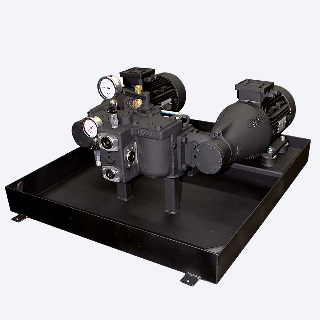
Search
Close this search box.

Compact Twin-pumping unit Series BIKO

hp-Twin-pumping unit in screwed-on or flanged (SAE flange to DIN ISO 6162) design are used as feed or pressure unit according to TRD 411 or TRD 604 and DIN 4755-2 must be constructed, tested, registered and labelled according to standard DIN EN 12514-1.

The BIKO series is available in 2 designs (L – light oil and S – HFO). It can optionally be used for 1- or 2-pipe system (simple conversion by the user). The selection for use a feed 1) or pressure unit is determined by the selection of pressure stages.

Technical Data:

Details and applications:

  • Flow rate: 1000 to 2000 l/h
  • operating pressure: 40 bar
  • operating temperature: 150°C

General Information

Viscosity range: The engine output of the units are designed for:

– BIKO-L up to 80 cSt.
– BIKO-S up to 150 cSt.

Please inquire about different options

max. permitted underpressure: Measured on the manometer item 7 ≤ -0.4 bar
max. system pressure: 5 bar
Casing material: EN-GJS 400

BIKO Schema 1-pipe-system

Scope of supply:

1 hp-Motor pump group
2 Filter
3 Integrated overflow valve
4 Switchover

5 Nonreturn valve
6 Oil pan
7 Vacuum gauge
8 Pressure gauge

BIKO Scheme 2-pipe-system

Optional accessories:

10 Pressure compensation device 2)
(pressure setting corresponding to selected pressure stage)
11 Leakage detector
12 Filter indicator (opt./ opt.-elec.)

Model key for determining order specifications

Series hp Hydraulics size hp Motor code Pressure stage Accessories
BIKO-L
Design for fuel oil EL + L, MDO/MGO

BIKO-S
Design for fuel oil M, S + ES, mineral tar oil


Hydraulics size

(see data tables)


Selection suited
to pressure needed

(see data tables)


2 = 2 – 9 bar

4 = 6 – 40 bar


LH Oil pan equipped
with leakage detector

DB Additional pressure compensation
device (safety valve set at:
Pressure stage 2 = 7 bar;
pressure stage 4 = 45 bar)

A Electrical auxiliary heating

E1 With optical filter indicator

E2 With optical and electrical filter indicator (E1 and E2)

Filterverschmutzungsanzeige
(E1 und E2)

1) When used as feed unit for fuel oil supply to DIN EN 12514, the maximum operating pressure of 6 bar must not be exceeded.

2) Additional protection against overpressure – optional integration into the suction or return line or directly into the tank.

Design for normal fuel

Design max. pressure 9 bar Design max. pressure 30 bar Design max. pressure 40 bar Device connections*
Suction Pressure & Return
Unit model
hp-Hydraulics size
Discharge at
1400 RPM at 0- 9 bar
hp-Motor code
Motor power [kW]
hp-Item no.:
Discharge at
1400 RPM at 30 bar
hp-Motor code
Motor power [kW]
hp-Item no.:
Discharge at
1400 RPM at 40 bar
hp-Motor code
Motor power [kW]
hp-Item no.:
Aggregate dimension
screw-fitted
flanged
screw-fitted
flanged
BIKO-L- 1 30 1 0,18 525050 800 x 675 G ¾” SAE ¾” G ½” SAE ½”
BIKO-L- 2 80 1 0,18 525052 60 1 0,18 525052 800 x 675 G ¾” SAE ¾” G ½” SAE ½”
BIKO-L- 3 120 1 0,18 525054 100 1 0,18 525054 800 x 675 G ¾” SAE ¾” G ½” SAE ½”
BIKO-L- 4 160 1 0,18 525056 140 3 0,37 525058 800 x 675 G ¾” SAE ¾” G ½” SAE ½”
BIKO-L- 5 300 1 0,18 525060 240 5 0,75 525062 200 5 0,75 525062 800 x 675 G ¾” SAE ¾” G ½” SAE ½”
BIKO-L- 6 450 3 0,37 525064 390 5 0,75 525066 360 6 1,1 525068 800 x 675 G ¾” SAE ¾” G ½” SAE ½”
BIKO-L- 7 600 3 0,37 525070 540 6 1,1 525072 480 7 1,5 525074 800 x 675 G ¾” SAE ¾” G ½” SAE ½”
BIKO-L- 8 1000 5 0,75 525076 700 7 1,5 525078 600 8 2,2 525080 900 x 800 G 1″ SAE 1″ G ¾” SAE ¾”
BIKO-L- 9 1500 5 0,75 525082 1200 8 2,2 525084 1000 9 3,0 525086 900 x 800 G 1″ SAE 1″ G ¾” SAE ¾”
BIKO-L- 10 2000 6 1,1 525088 1700 9 3,0 525090 1400 10 4,0 525092 900 x 800 G 1″ SAE 1″ G ¾” SAE ¾”
BIKO-L- 11 3000 7 1,5 525094 2200 10 4,0 525096 2000 11 5,5 525098 1100 x 950 G 1½” SAE 1½” G 1¼” SAE 1¼”
BIKO-L- 11-1 3700 7 1,5 525100 3000 10 4,0 525102 2700 11 5,5 525104 1100 x 950 G 1½” SAE 1½” G 1¼” SAE 1¼”
BIKO-L- 12 4500 8 2,2 525106 3600 11 5,5 525108 3200 12 7,5 525110 1100 x 950 G 1½” SAE 1½” G 1¼” SAE 1¼”
BIKO-L- 13 6000 9 3,0 525112 4800 12 7,5 525114 1100 x 950 G 1½” SAE 1½” G 1¼” SAE 1¼”
BIKO-L- 14 6700 9 3,0 525116 5800 12 7,5 525118 1100 x 950 G 1½” SAE 1½” G 1¼” SAE 1¼”

Design for HFO

Design max. pressure 9 bar Design max. pressure 30 bar Design max. pressure 40 bar Device connections*
Suction Pressure & Return
Unit model
hp-Hydraulics size
Discharge at
1400 RPM at 0- 9 bar
hp-Motor code
Motor power [kW]
hp-Item no.:
Discharge at
1400 RPM at 30 bar
hp-Motor code
Motor power [kW]
hp-Item no.:
Discharge at
1400 RPM at 40 bar
hp-Motor code
Motor power [kW]
hp-Item no.:
Aggregate dimension
screw-fitted
flanged
screw-fitted
flanged
BIKO-S- 1 50 1 0,18 525150 45 1 0,18 525150 800 x 675 G ¾” SAE ¾” G ½” SAE ½”
BIKO-S- 2 90 1 0,18 525152 80 1 0,18 525152 800 x 675 G ¾” SAE ¾” G ½” SAE ½”
BIKO-S- 3 130 1 0,18 525154 125 3 0,37 525156 800 x 675 G ¾” SAE ¾” G ½” SAE ½”
BIKO-S- 4 170 1 0,18 525158 165 3 0,37 525160 800 x 675 G ¾” SAE ¾” G ½” SAE ½”
BIKO-S- 5 320 1 0,18 525162 300 5 0,75 525164 295 5 0,75 525164 800 x 675 G ¾” SAE ¾” G ½” SAE ½”
BIKO-S- 6 475 3 0,37 525166 450 6 1,1 525168 435 7 1,5 525170 800 x 675 G ¾” SAE ¾” G ½” SAE ½”
BIKO-S- 7 620 3 0,37 525172 600 7 1,5 525174 590 8 2,2 525176 800 x 675 G ¾” SAE ¾” G ½” SAE ½”
BIKO-S- 8 1100 5 0,75 525178 950 8 2,2 525180 900 9 3,0 525182 900 x 800 G 1″ SAE 1″ G ¾” SAE ¾”
BIKO-S- 9 1625 5 0,75 525184 1475 9 3,0 525186 1425 10 4,0 525188 900 x 800 G 1″ SAE 1″ G ¾” SAE ¾”
BIKO-S- 10 2150 6 1,1 525190 2050 10 4,0 525192 1975 11 5,5 525194 900 x 800 G 1″ SAE 1″ G ¾” SAE ¾”
BIKO-S- 11 3225 7 1,5 525196 3000 11 5,5 525198 2900 12 7,5 525200 1100 x 950 G 1½” SAE 1½” G 1¼” SAE 1¼”
BIKO-S- 11-1 3900 8 2,2 525202 3700 11 5,5 525204 3650 12 7,5 525206 1100 x 950 G 1½” SAE 1½” G 1¼” SAE 1¼”
BIKO-S- 12 4825 8 2,2 525208 4750 12 7,5 525210 4725 12 7,5 525212 1100 x 950 G 1½” SAE 1½” G 1¼” SAE 1¼”
BIKO-S- 13 6100 9 3,0 525214 5600 1100 x 950 G 1½” SAE 1½” G 1¼” SAE 1¼”
BIKO-S- 14 6800 9 3,0 525216 6550 1100 x 950 G 1½” SAE 1½” G 1¼” SAE 1¼”

The twin-pumping units of the BIKO series are currently under development. Therefore, not all sizes are available.
Please send your request.

Need additional infos? Please contact us

Jochen Twellaar

+49 (0) 721/95618-23

twellaar@hptechnik.com

Joachim Rau

+49(0) 721/95618-25

rau@hptechnik.com