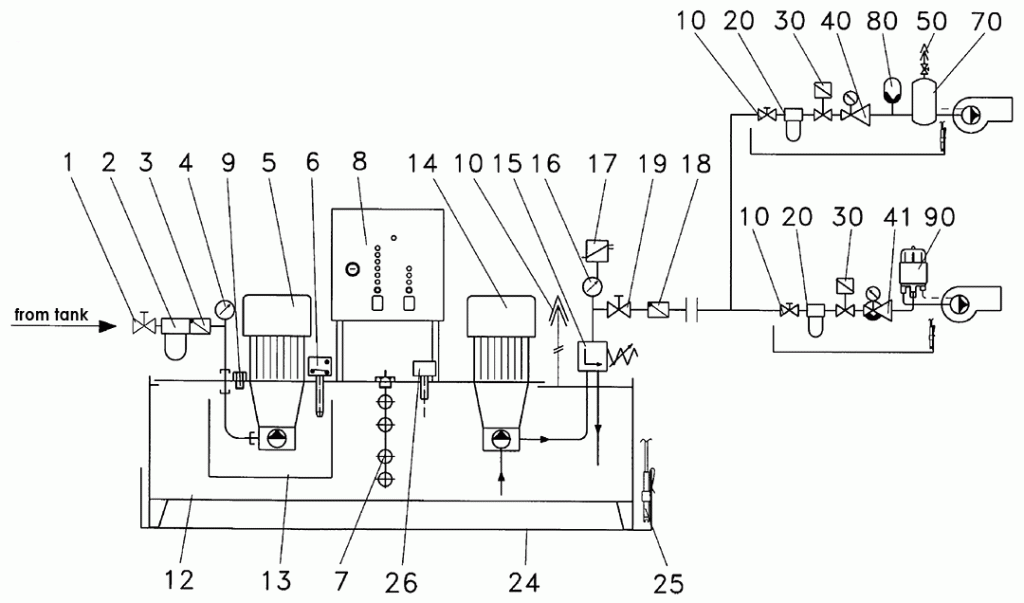
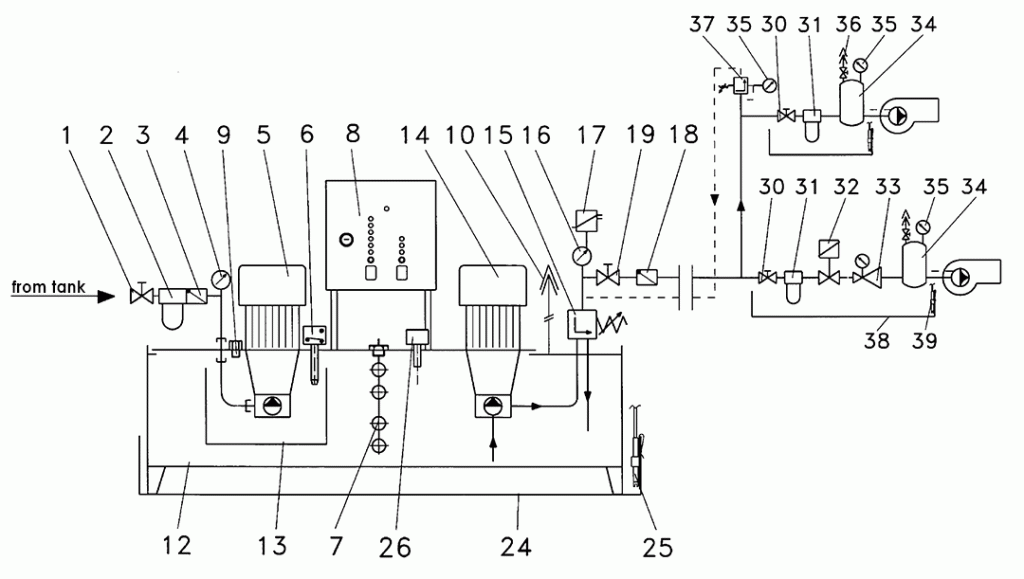
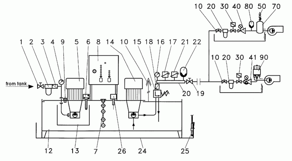
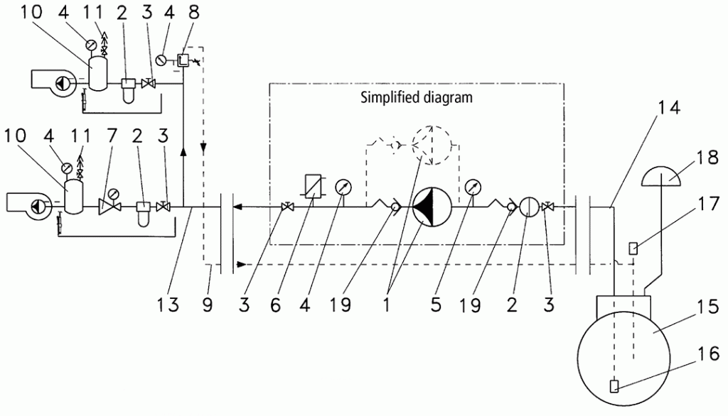
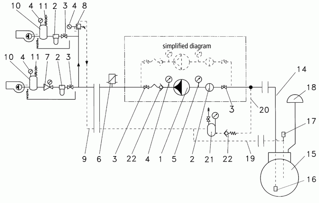
Single-pipe oil supply of oil burners with independently controlling hp-Single suction and pressure pump aggregates without bypass, aggregates pressure control systems for intermittent operation
Name:
1 Ball valve (in the place of installation)
2 Filter
3 Nonreturn valve
4 Vacuum gauge
5 hp-Internal gear pump with standard electric motor
6 Thermostatic switch
7 Level sensor
8 hp-Pump control
9 Filling port
10 Air discharge port
12 Operating tank
13 Oil bath chamber
14 hp-Internal gear pump with standard electric motor
15 hp-Overflow valve
16 Pressure gauge
17 min. pressure switch
18 Nonreturn valve
19 Ball valve
20 Oil distributor
21 Working backlash of pressure switch
22 Membrane pressure accumulator
24 Oil pan
25 Leakage detector
Accessories:
26 Additional spill protection to VbF and WHG
Combination:
Single-pipe oil supply with the suction unit part of the suction-pressure pump aggregate and
Two-pipe oil supply of oil burners in continuous operation with bypass to suction-pressure pump aggregate
hp-Single suction and pressure pump unit
with self-activating pressure accumulator control system
without bypass to the operating tank
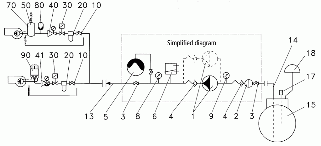
Single-pipe oil supply of oil burners with independently controlling hp feeder units
To DIN/EN 12514 without bypass to the tank
Scope of supply:
1 hp-Pump with overflow valve
2 Filter
3 Ball valve
4 Nonreturn valve
5 Membrane pressure accumulator
6 Pressure switch or pressure transmitter
8 Pressure gauge
9 Vacuum gauge
13 Pressure pipe
14 Suction pipe
15 Tank
17 Filling port
18 Air discharge port
Two-pipe oil supply of oil burners with hp-Feed pump aggregate to DIN/EN 12514 and DIN 4755, part 2 without overflow valve (item 8) and bypass to tank (item 9)
For single pipe system, there is no overflow valve (item 8) and bypass line to the tank (item 9)
For single pipe system, the electrical control must be designed for intermittent operation. The single pipe pressure is maintained by the adjustable overflow valve integrated into the pump.
Scope of supply:
1 hp-Pump with overflow valve
2 Filter
3 Ball valve
4 Pressure gauge
5 Vacuum gauge
6 Pressure switch
7 Pressure-regulator with upstream solenoid valve
8 hp-Overflow valve
9 Bypass lines
10 Vessel
11 Automatic float air vent for single pipe system
13 Pressure pipe
14 Suction pipe
15 Tank
16 Foot valve
17 Filling port
18 Air discharge port
19 Nonreturn valve
Two-pipe oil supply of oil burners with hp-Feed pump aggregate to DIN/EN 12514 and DIN 4755, part 2 without overflow valve (item 8) and bypass to tank (item 9)
For single pipe system, there is no overflow valve (item 8) and bypass line to the tank (item 9)
For single pipe system, the electrical control must be designed for intermittent operation. The single pipe pressure is maintained by the adjustable overflow valve integrated into the pump.
Scope of supply:
1 hp-Pump with overflow valve
2 Filter
3 Ball valve
4 Pressure gauge
5 Vacuum gauge
6 Pressure switch at place of installation or “S” accessories
7 Pressure-regulator with upstream Solenoid valve
8 hp-Overflow valve
9 Bypass line
10 Vessel
11 Air vent
12 Pressure pipe
14 Suction pipe
15 Tank
16 Foot valve
17 Filling port
18 Air vent
19 Bypass line to tank only for over-ground bypass line and tank
20 Alternative connection of the bypass line to the suction line for earthing line and earthing tank In this case there is no Bypass line adapter 19
21 Degassing vessel with ventilation e.g. by automatic float air vent
22 Nonreturn valve, Pre-tension 1 bar

